APL-2 Series Limit Switch Box
Installation Operation & Maintenance Manual
Doc No. : HUMG-APL2-16 Rev0 Page 6 / 10 Valve Automation Leader HKC
Ø Un-tighten the captive cover bolts with an applicable tool. (Spanner.+ Driver recommended)
Ø Remove the cover carefully.
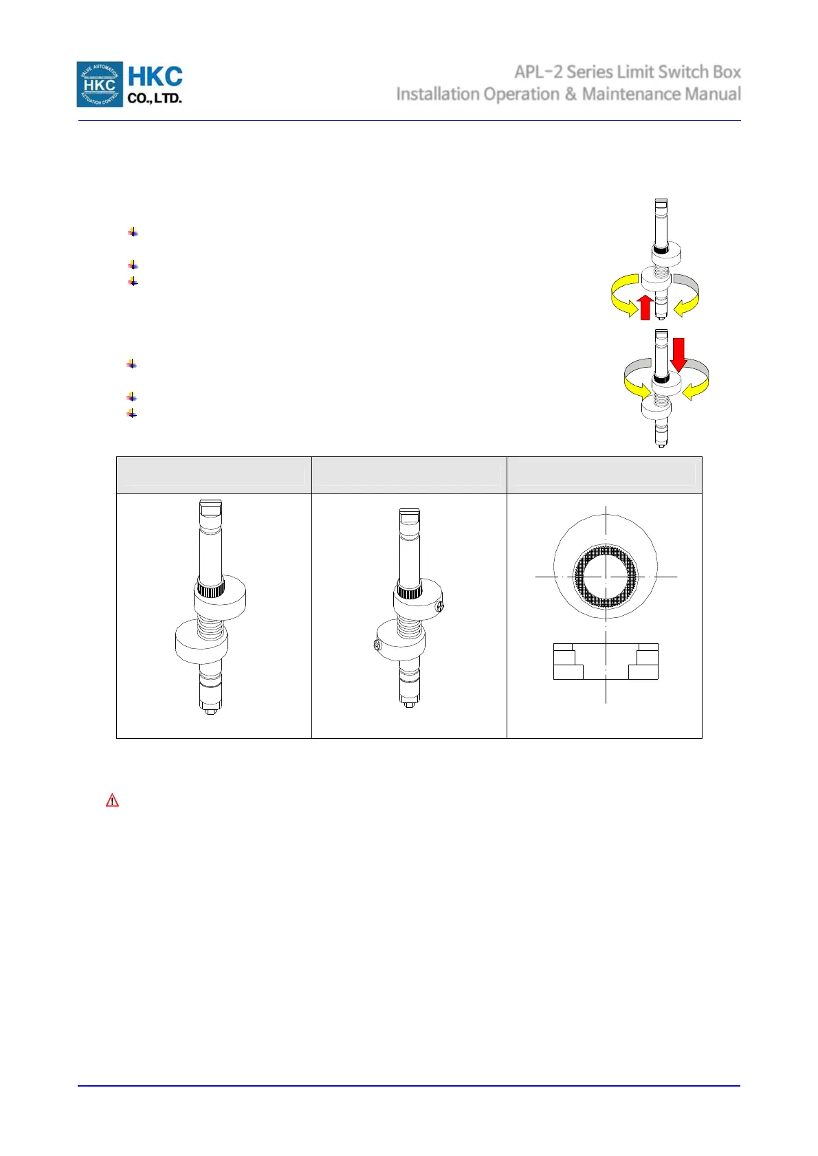
Ø Open cam setting
Electric power or air supply of valve actuator on to operate the actuator fully
open
Lift the bottom yellow cam up and rotate it until the switch is activated.
And then release it. Cam shall be back into a stable position by itself.
Ø Close cam setting
Electric power or air supply of valve actuator off to operate the actuator fully
close
Push the upper cam down and rotate it until the switch is activated.
And then release it. Cam shall be back into a stable position by itself.
7.4 Wiring
Danger ;
HAZARDOUS VOLTAGE. No electrical power should be connected until all wiring and limit switch
adjustments have been completely.
APL limit switch box enclosure feature prewired switches. All user connections are made at a numbered terminal
strip. A wiring diagram, located inside the cover, indicates which terminal numbers correspond to switch
contacts, such as normally open (NO), normally closed (NC), etc. Follow the wiring diagram and electrical code
to connect the switches to your system.
Solenoid valve may also be wired through the APL enclosure. Two auxiliary terminals are included as standard.
APL limit switch box has two cable entries on the body and supply a blanking plug not a cable gland which meet
the type of protection. Cable gland shall be applied by installer or user.
 Loading...