Do you have a question about the HNC Electric HV590 Series and is the answer not in the manual?
General information and notes regarding the manual.
Defines categories of safety warnings (Warning, Caution).
Safety measures to take before installing the inverter.
Safety measures during installation and wiring phases.
Safety checks and precautions before powering on the inverter.
Safety measures to follow during operation and maintenance.
Precautions concerning motor insulation, thermal protection, and performance.
Precautions for high frequency, vibration, voltage differences, and output devices.
Proper use of switching devices and EMC considerations.
Guidelines for grounding and wiring to ensure good EMC.
Recommendations for installing input filters for EMC compliance.
Information on nameplate, model, series, and standard specifications.
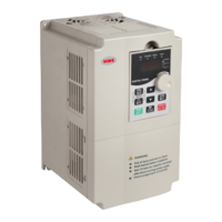
Details on product shape, outline, dimensions, and interface configuration.
Recommended environmental conditions and safe handling procedures.
Steps for installation, wiring, and terminal connections.
Detailed arrangement and description of control and main circuit terminals.
Adding a standby circuit for enhanced security and reliability.
Diagram showing connections between the inverter and external devices.
Details on external components, their functions, and mounting dimensions.
Overview of the keyboard layout, display interface, and button functions.
Guides on parameter setting, modification, and motor auto-tuning.
Parameters for monitoring inverter status and basic operational functions.
Parameters for motor type selection, control modes, and tuning.
Parameters for V/F control and Vector control modes.
Configuration of input/output terminals, operation modes, and advanced features.
Parameters related to overload protection, fault handling, and system safeguards.
List of fault codes, possible causes, and solutions for inverter issues.
Analysis and solutions for frequently occurring inverter faults.
Daily and regular inspection checklist for inverter upkeep.
Guidelines for regular component replacement, storage, and safety.
Details of the H5RS485 card and RS485 communication protocol.
Mapping of function codes to communication parameter addresses.
Default settings for monitoring, basic functions, and motor parameters.
Default settings for control modes, terminals, and operation.
Default settings for advanced functions, protection, and communication.
Table detailing brake unit models and required braking resistor specifications.
Specifications for input and output AC reactors, including dimensions.
| Feedback | Encoder, Resolver |
|---|---|
| Input Voltage | 380-480 VAC |
| Control Method | Vector Control, V/F Control |
| Operating Temperature | -10°C to 50°C |
| Protection | Overcurrent, Overvoltage, Undervoltage |
| Communication | Modbus, CANopen, Profibus |
| Power Range | 0.4kW~560kW |
| Cooling Method | Air Cooling |
| Relative Humidity | ≤95% (Non-condensing) |
| Altitude | ≤1000m (Above sea level) |