Do you have a question about the HNC Electric HV610 Series and is the answer not in the manual?
Safety guidelines and important notes for using the inverter.
Steps and methods for checking the product after purchase to ensure it's correct.
Details about the information presented on the inverter's nameplate.
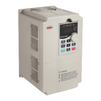
Identification and description of the physical parts of the frequency inverter.
Guidelines for physically installing the frequency inverter in its operating environment.
Specifies environmental and site conditions required for proper inverter installation.
Details on the necessary clearance and space around the inverter for heat dissipation.
Instructions and precautions for wiring the frequency inverter's power and control circuits.
Description of the terminals for the main power circuit connections.
Guidance on wiring the main circuit and important considerations for safe installation.
Detailed explanation of the terminals for the control loop circuits.
Visual representation of typical wiring connections for the frequency inverter.
Explains different wiring methods for control circuits, including analog and digital inputs.
Overview of the front panel's keyboard and display for controlling and monitoring the inverter.
Explanation of the status indicated by various indicator lights on the operation panel.
Details the function of each key on the frequency inverter's operation panel.
Describes the three-level menu structure for accessing and changing parameters.
Provides methods for quickly searching and accessing specific function codes.
Outlines the three operation control modes (keyboard, terminal, RS-485).
Explains how to set motor parameters for optimal performance, including self-learning.
Overview of basic functional parameters grouped by function codes (F0 group).
Detailed description of parameters in the F0 group related to basic functions.
Lists common faults, their causes, and corresponding troubleshooting steps.
Provides guidance on common issues encountered during commissioning and their solutions.
Addresses common problems specifically for V/F control mode and their resolutions.
Detailed breakdown of fault analysis and countermeasures for various error codes.
General instructions and safety precautions for maintaining and repairing the inverter.
Describes regular inspection items to ensure the inverter's optimal performance and longevity.
Details regular inspection procedures for hard-to-reach areas and cleaning.
Lists common vulnerable parts and their typical lifespan for replacement planning.
Guidelines for proper temporary and long-term storage of the frequency inverter.
Illustrates the connection of peripheral equipment and optional accessories.
Describes the functions of various peripheral devices used with the inverter.
Explains the purpose and selection of circuit breakers and contactors.
Details the function and benefits of using an AC input reactor.
Explains the purpose and application of AC output reactors.
Guides on selecting braking units and resistors for energy dissipation.
Information on externally connecting DC reactors.
Explains the function and importance of radio noise filters for EMC.
Details the function and installation of leakage protectors for safety.
Describes the use of capacitance boxes for continuous operation during power failures.
Outlines the company's commitment to product quality and warranty terms.
Covers fundamental settings for communication protocols and parameters.
Explains how to select the communication protocol, defaulting to MODBUS.
Details the configuration of data transmission rates (baud rates) for communication.
Specifies the data formats for communication, including error checking options.
Instructions for setting the unique Modbus address for each inverter.
Configures timeout settings for communication to detect failures.
Describes the Modbus interface and its function codes for parameter management.
Details Modbus function codes and their corresponding information formats.
Maps function codes to Modbus register addresses for read/write operations.
Describes the register for controlling frequency/torque via communication.
Lists addresses for reading inverter status and parameters.
Register for controlling inverter operations like run, stop, jog via communication.
Controls the state of output terminals via communication.
Controls analog output AO1 via communication with quantization.
Controls analog output AO2 via communication with quantization.
Controls pulse output FMP via communication with quantization.
Monitors the current running status of the frequency inverter.
Monitors the current fault code of the frequency inverter.
Core functional specifications of the HV610 series frequency inverters.
Illustrates the dimensions for keyboard operation in two configurations.
Provides mounting dimensions and hole sizes for the keyboard bracket.
Shows dimensions and mounting details for specific plastic shell models.
Displays dimensions and mounting information for other plastic shell models.
Illustrates dimensions and mounting for sheet metal machine enclosures.
Shows dimensions and mounting for larger sheet metal machine enclosures.
Provides a general overview of PID closed-loop control for constant pressure applications.
Describes the two types of pressure sensors used for control.
Shows wiring diagrams for both types of pressure sensors.
Details parameter settings for a 0-10V remote pressure gauge system.
Explains the sleep and wake-up functions based on pressure or frequency thresholds.
| Cooling Method | Forced Air Cooling |
|---|---|
| Protection | Overcurrent, overvoltage, undervoltage, overload, short circuit |
| Communication | RS485, Modbus RTU |
| Ambient Temperature | -10°C to +40°C |
| Storage Temperature | -20°C to +60°C |
| Relative Humidity | ≤95% (non-condensing) |
| Altitude | ≤1000m (above sea level) |