- 4 -
SETTING UP THE RCS-BELTROL ESC’s.
THESE INSTRUCTIONS REFER TO THE HOBBY KING TR6a 2.4 GHz 6 CHANNEL R/C.
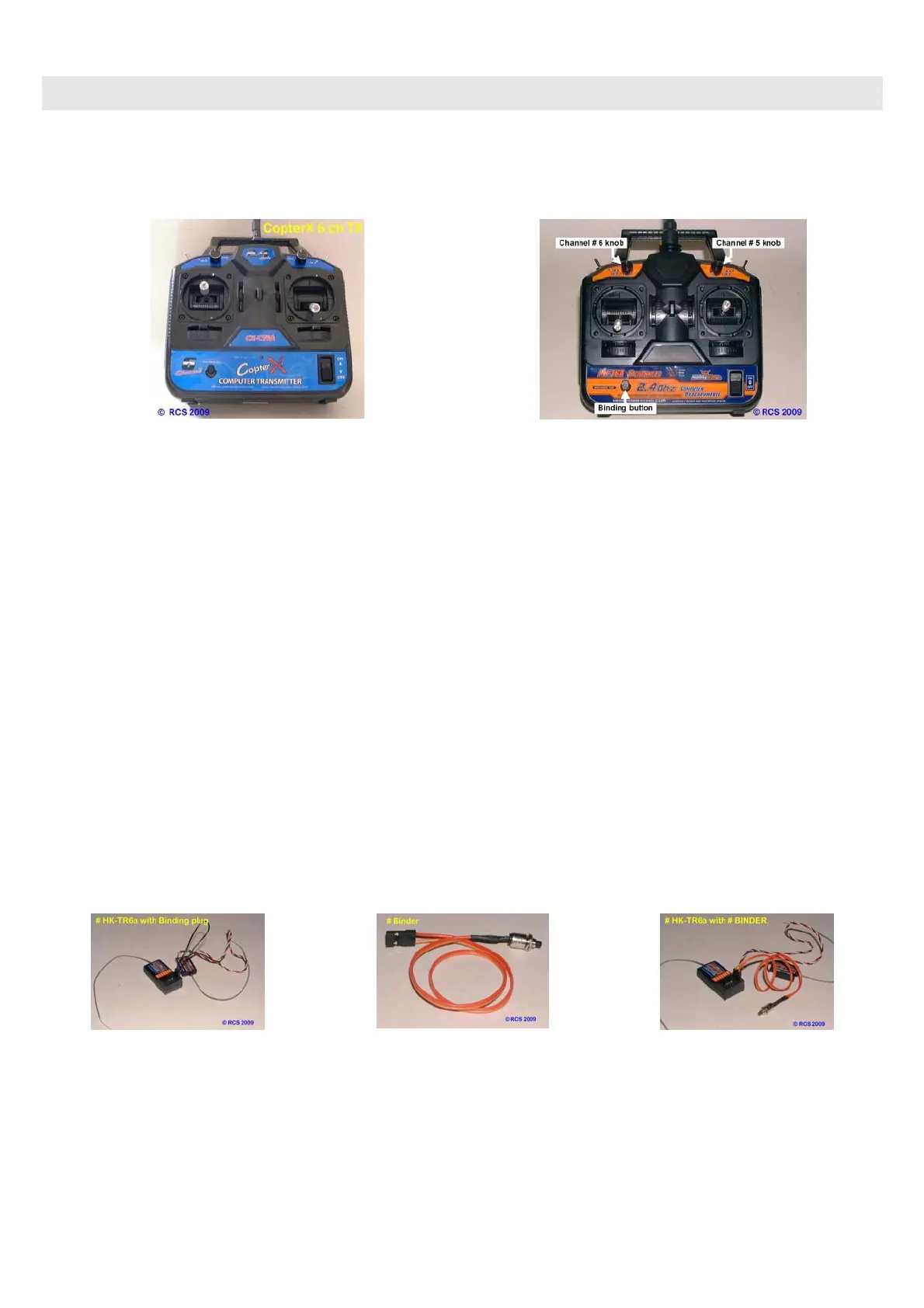
LAYOUT OF THE HK-T6a TRANSMITTER. YOU CAN USE EITHER MODE # 1 or MODE # 2.
YOUR SYSTEM WILL LIKELY BE DELIVERED CORRECTLY SET UP FOR THE MODE. HOWEVER IT IS A
GOOD IDEA TO CHECK THE SETTINGS VIA THE SUPPLIED COMPUTER PROGRAM. SEE PAGE # 8.
Shown above is a Mode # 1 TX.
The Elevator & Rudder stick is on the left.
The Throttle & Aileron stick is on the right
Shown above is a Mode # 2 TX.
The Elevator & Rudder stick is on the right.
The Throttle & Aileron stick is on the left
Prior to using this system there are two procedures that must be carried out by the operator.
1. “BINDING”.
The 1st procedure is to “BIND” the CX-CR6a receiver (RX) to the Transmitter (TX).
“BINDING” is accomplished by following a few simple steps that are outlined in the R/C system instructions.
In case you don’t have those instructions here is how we go about it.
Although the RCS-BELTROL program ignores the RX Fail Safe commands, before “BINDING” the operator
should nevertheless set up the failsafe as COPTER-X intended.
The operator must have the spring loaded TX stick positions in neutral & the throttle stick to down (zero).
All the servo reversing switches must be set to normal. (Only settable with the computer program).
Firstly set up the TX trim tabs on all four control sticks. These MUST be in the middle.
The HK T6a TX has regular slide type trim tabs.
There is no Ch # 5 switch on the TX. Knob “A” must be rotated fully clockwise to be in the OFF position.
The two switches “A” & “B” must be OFF. i.e pushed backwards away from you. They are not used.
Once the trim tabs are in neutral you can proceed with the “BINDING” process.
The TRIM tabs are easy to accidentally move. Re-centre them occasionally. No need to rebind.
HOW TO “BIND”.
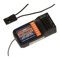
1.1 Firstly insert the “BINDING” plug supplied with the R/C system into the “BINDING” socket on the RX. This
means gaining access to the RX. If the RX is buried inside the loco we recommend you use a servo extension
lead or the # BINDER to get access. Press & hold the # BINDER pushbutton only when “binding” RX to TX.
1.2 Turn the loco power ON. The loco will always give a very slight jerk at switch ON. See page # 9.
The RX LED will start blinking slowly to indicate it is ready to be bound.
Please note the green LED on the ESC pcb & the front and rear lights (if fitted) will stay OFF.
1.3 Press the “BINDING” button on the TX and hold it in position.
1.4 Turn the TX power switch to ON. Almost immediately the LED on the RX will stop blinking & go solid ON.
1.5 Remove “BINDING” plug (or release # BINDER pushbutton) & store it safely.
1.6 Turn both loco & TX OFF.
1.7 Turn loco ON & the ESC LED & both loco lights will immediately blink three times & then go to solid ON.
1.8 The R/C system is ready for speed calibration.
 Loading...