to attach wires to three (3)
Figure 2, "Current Transform
(above) to install the three (3) current transformers. Clamp a single
current transformer on each of the three (3) power wires connected
otor. The sides of the current transformers, with the white
text printed on the CT's case,
all be pointed in the same
must all be pointed in the same must
direction (CT signals in phase).
Spacing between the 3 adjacent CTs, shown in
Figure 4, "Model 610 3 Phase
connect the current transformer's
wires to the Model 610 Digital Current Monitor's CT terminals
Connect 24VAC power, as shown in
terminal to a 24 VAC source
The Model 610 uses Clamp-On Current Transformers (CTs)
to monitor the current flowing through each motor's power
wire that is equipped with a current transformer. The CTs are
. When more then one (1) CT is
be oriented in the same direction, as shown in
Transformer Alignment (below)Transformer Alignment
to provide accurate in-phase
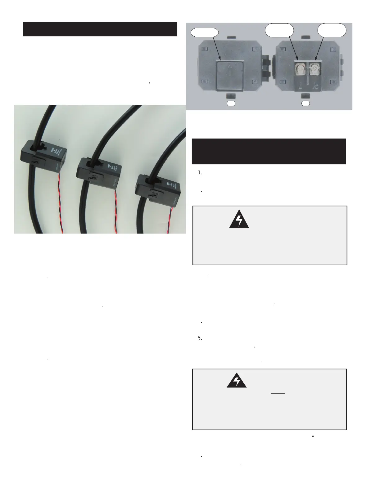
Remove plastic tab shown on CT's bottom, pictured
Figure 3A "Two Current Traneformer's Bottoms",
tab between a finger and small screw driver blade then twisting.
The tab will fly off if removed with only the screw driver blade.
required length of supplied 12 foot long required length of
twisted pair wire to reach between the CT and the Model
f additional CT wire is needed, use 22 AWG (mini-
mum) stranded, twisted pair cable properly insulated for the
application. The maximum length of additional
Attach one end of the black
Replace the plastic tab removed in sub-step
To protect 3 phase across-the-line motors, proce
Phase, Across-the-Line, Motor Installation
To protect single phase motors, proceed to the
To protect 3 phase part (split) winding motors, proce
To monitor compressor temperatures, proceed to the
pressor Temperature Sensing Information
To operate the Model 610 remotely, proceed to the
3 Phase, Across the Line,
Motor Installation
Disconnect power from the motor(s) and ensure the motor(s)
is/are electrically disabled prior to the Model 610 Digital
Current Monitor's installation.
Installation Con't
Current Transformer wires
the Model 610 Digital Current Monitor's terminal
block before operation of the motor. The Current
Transformers will generate high voltages if the wires
are left unconnected (open circuited).
Current Transformer Alignment
Two Current Transformer's Bottoms
 Loading...