EasyManua.ls Logo

Hoffman Controls 610 Series - Page 5

Default Icon
20 pages
Print Icon
To Next Page IconTo Next Page
To Previous Page IconTo Previous Page
Loading...
9
.
If an
alarm notification is desired, connect the alarm's 24
VAC wires to the
ALARM
relay's
N.O.
and
COM
terminals.
10.
If compressor temperature sensing or Modbus RTU
communication is desired,
refer to
Figure 9,
Model 610 Exhaust
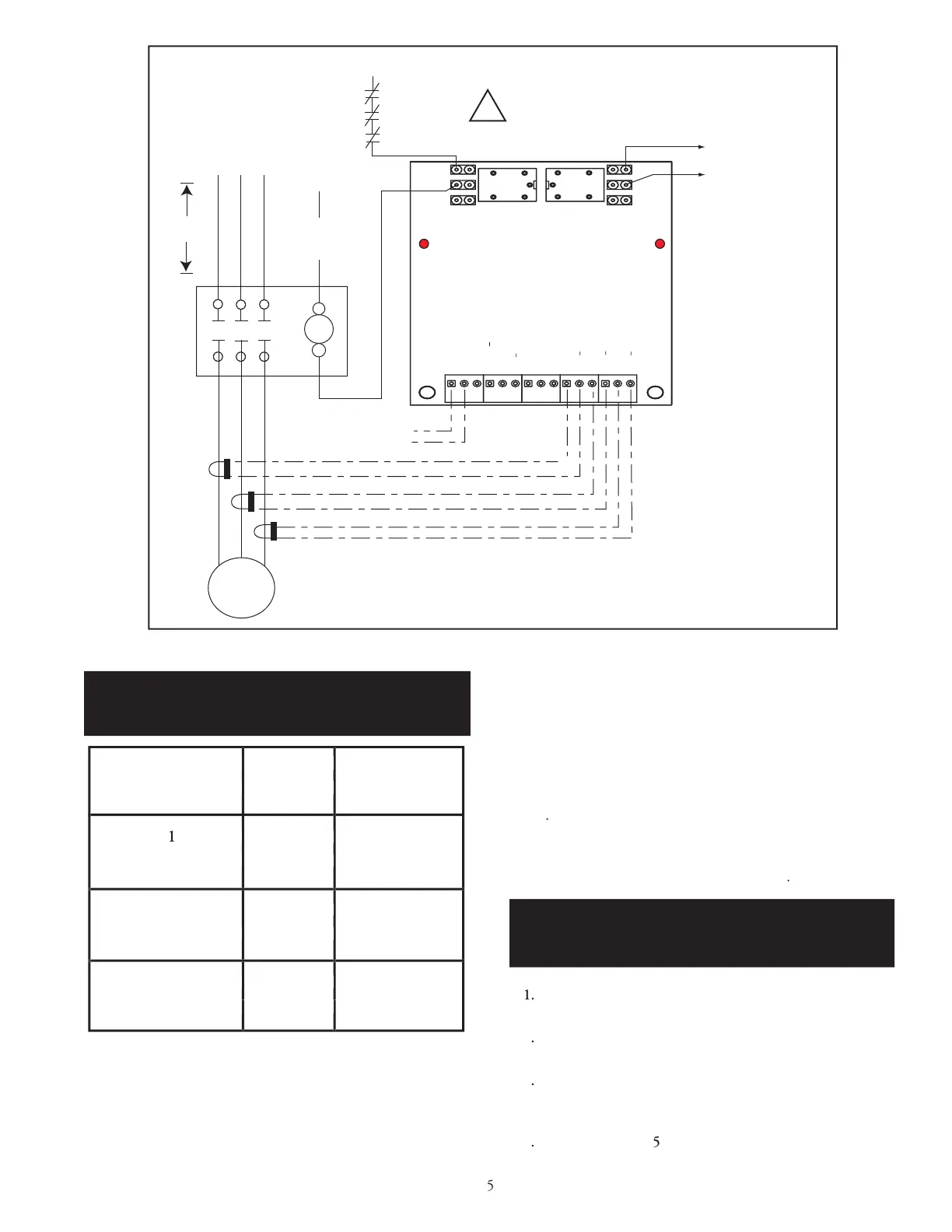
Sensor, Oil Sensor and Modbus Wiring Diagram (
page 13
)
and
the
Compressor Temperature Sensing Information
section (page
12) and / or the
Modus RTU Installation
section (page 15)
for
details
.
11.
This completes the
3 Phase, Across-the-Line, Motor's Model
610 Digital Current Monitor's hardware installation. Continue
with the
Normal Operation
section on
page 11
.
1
.
Disable
all line power going to the
motor contactor and
m
otor.
2
.
Refer to
Installation
Section step
8
, on page 4,
t
o attach the
CT's
wires.
3
.
Refer to
Figure 2, "Current Transformer Alignment"
(page
4) to install the single clamp-on current transformer
(CT) on the
power wire connected to the m
otor.
4
.
Referring to
Figure
5
, Model 610 Single Phase Wiring
Diagram (
page 6
)
, connect the current transformer's
wires to the
5
3 Phase, Across-the-Line,
Current Transformer
Wiri
ng Chart
TABLE 1
8
.
Connect
the
TRIP
relay's
COM
terminal to the 24 VAC side
of the motor contactor's coil
as
shown in
Figure
4
.
































































Single Phase Motor
Installation
3 Phase, Across the Line,
Motor Installation Con't
Motor Contactor CT Wire Model 610
Load Terminal Color PCB Terminal
T
1
Red CT1+
Black CT1-
T2
Red
CT2+
Black CT2-
T3
Red CT
3+
Black CT3-
Motor Contactor CT Wire Model 610
Load Terminal Color PCB Terminal
Red CT1+
Black CT1-
Black CT2-
Red CT
Black CT3-
Motor Contactor CT Wire Model 610
Load Terminal Color PCB Terminal
Red CT1+
Black CT1-
CT2+
Black CT2-
Red CT
Black CT3-

Related product manuals