EasyManua.ls Logo

Hoffman Controls 610 Series - Page 6

Default Icon
20 pages
Print Icon
To Next Page IconTo Next Page
To Previous Page IconTo Previous Page
Loading...
6

��������������


























































8
.
Connect
the
TRIP
relay's
COM
terminal to the 24VAC side
of the motor contactor's coil,
as shown in
Figure
5
.
9
.
If an
alarm notification is desired connect the alarm's 24
VAC
wires to the
ALARM
relay's
N.O.
and
COM
terminals,
as shown
in
Figure
5
.
10.
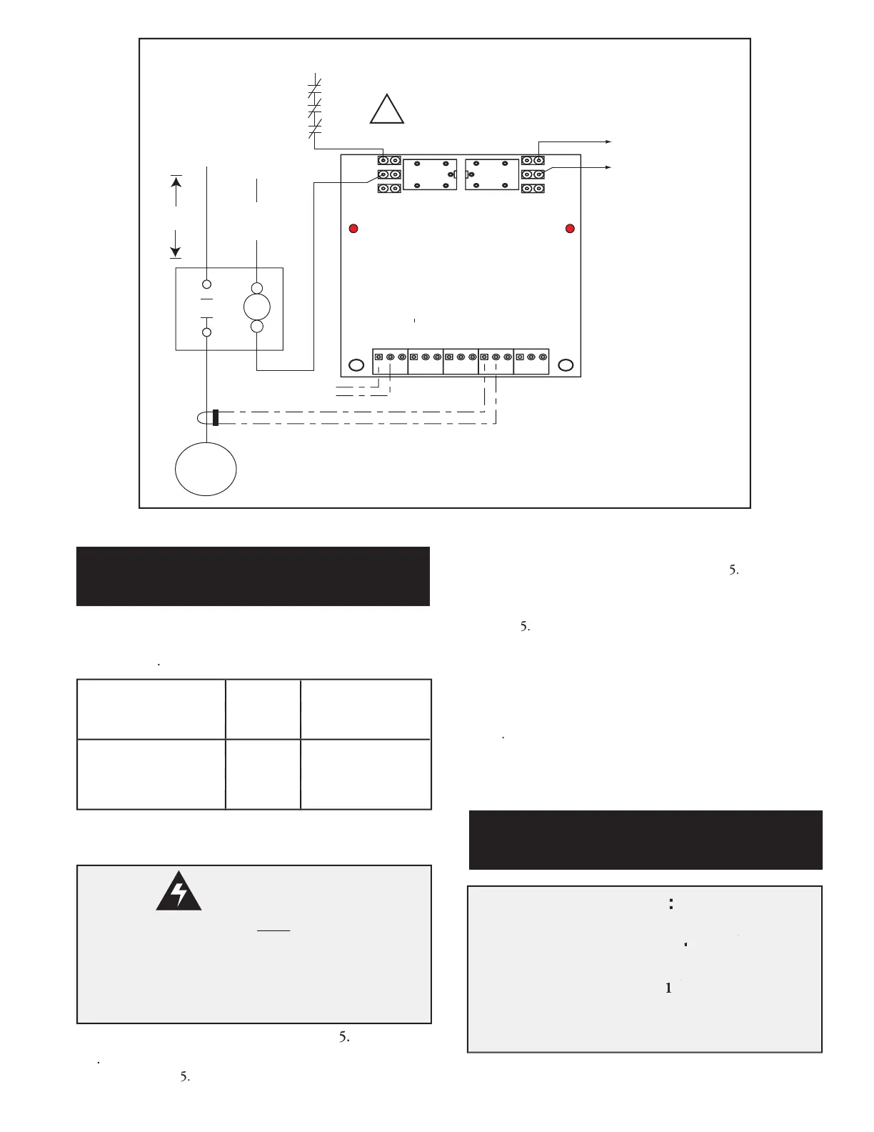
If compressor temperature sensing or Modbus RTU com-
munication is desired,
refer to
Figure
9
,
Model 610 Exhaust
Sensor, Oil Sensor and Modbus Wiring Diagram
(
page 13
)
and
the
Compressor Temperature Sensing Information
section (page
12) and / or the
Modus RTU Installation
section (page 15)
for
details
.
11.
This completes the
Single
Phase Motor's
610 Digital
Current Monitor's hardware installation.
Continue with the
Normal Operation
section on page 11.
Single Phase Motor
Installation Con't
NOTE
:
T
he Model 610 Digital Current Monitor
allows a
he Model 610 Digital Current Monitor allows a he Model 610 Digital Current Monitor
part (
split) winding
motor's 2
nd
he Model 610 Digital Current Monitor
nd
he Model 610 Digital Current Monitor
circuit to ener-
nd
circuit to ener-
nd
gize for an operator selectable 2.0 to 30.0 seconds,
after power is applied to the
1
st
gize for an operator selectable 2.0 to 30.0 seconds,
st
gize for an operator selectable 2.0 to 30.0 seconds,
part (split) wind-
st
part (split) wind-
st
ing circuit,
prior to checking for
phase rotation
errors or phase imbalance issues
.
The default is 3.0
seconds.
Part (Split) Winding Motor
Information
Model 610 Digital Current Monitor's CT1 terminals
a
s shown
in
TABLE 2, "
Single Phase
Current Transformer Wiring
Chart
",
below
.
Single Phase Current Transformer
Wiring Chart
TABLE 2
6
.
Connect 24VAC power as shown in
Figure
5
.
7
.
Connect
the
TRIP
relay's
N.C.
terminal to a 24 VAC source
as shown in
Figure
5
.
Motor Contactor CT Wire Model 610
Load Terminal Color PCB Terminal
T
1 Red CT1+
Black CT1-
Motor Contactor CT Wire Model 610
Load Terminal Color PCB Terminal
1 Red CT1+
Black CT1-
Motor Contactor CT Wire Model 610
Load Terminal Color PCB Terminal
1 Red CT1+
Black CT1-
WARNING:
Current Transformer wires
must
be c
must be cmust
onnected to
the Model 610 Digital Current Monitor's terminal
block before operation of the motor. The Current
Transformers will generate high voltages if the wires
are left unconnected (open circuited).

Related product manuals