EasyManua.ls Logo

Hoffman Controls 610 Series - Page 7

Default Icon
20 pages
Print Icon
To Next Page IconTo Next Page
To Previous Page IconTo Previous Page
Loading...
7









































































Part (
s
plit)
winding motors can be protected, using either one
(1) or two (2) Model 610
Digital
Current Monitors, by following
one of the two methods shown below and on the next page:
Method 1:
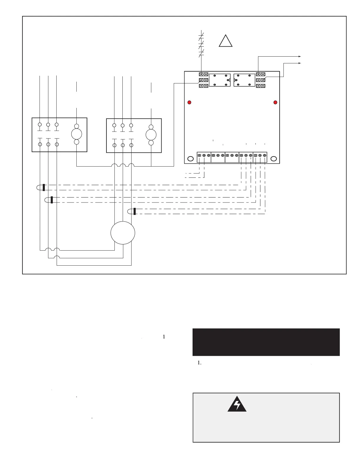
This method uses only one (1) Model 610
Digital
Current Monitor
by placing two CTs on
Starter
A
phases
A phases A
T
1
and
T
2
, and placing the third CT on the
Starter
B's
phase
T
3
. Set the
phase imbalance trip point at 29% or less. The current trip level
should be the motor's FLA times 1.08 (8% about the FLA). This
method will protect against all major faults in either part winding.
Method 2:
This method uses two (2) Model 610 monitors by
placing one (1) CT on each power wire connected to both of the
Starter A
and
Starter A and Starter A
Starter B
motor contactor's
T1
,
T2
and
T3
termi-
nals (total of
6 CTs)
.
This method provides complete coverage.
The selected trip current level, used by each Model 610, should be
1/2 FLA
(the current allowed in each part winding) times 1.08 for
8% over current
protection
.
To protect a 3 phase part (split) winding motor, using a single
Model 610
Digital
Current Monitor (
M
ethod 1), proceed to the
Single 610 Part (Split) Winding Motor Installation
section below.
To protect a 3 phase part (split) winding motor, using two
Mod-
el 610
Digital
Current Monitors (
M
ethod 2), proceed to the
Dual
610 Part (Split) Winding Motor Installation
section on page 8.
1
.
Disable all line pow
er going to both the
Starter A
and
Starter A and Starter A
Starter
B
motor contactors and motor.
2.
Refer to
Installation
Section step
8
, on page 4,
to attach wires
to three (3) CTs.
Single Model 610 Part (Split) Winding Motor Wiring Diagram
Figure 6
Single 610 Part (Split) Winding
Motor Installation
WARNING:
Disconnect power from the motor(s) and ensure the motor(s)
is/are electrically disabled prior to the Model 610 Digital
Current Monitor's installation.

Related product manuals