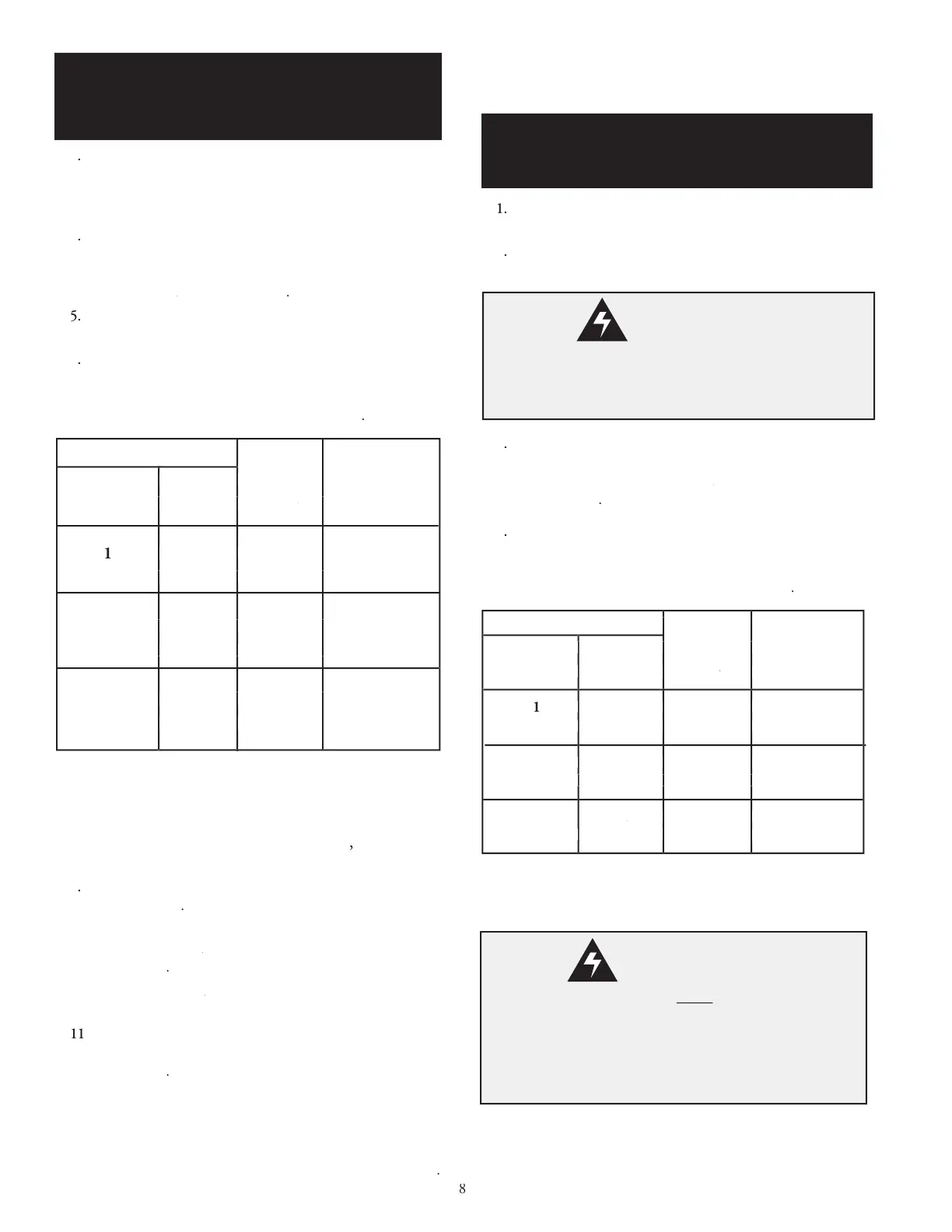
Figure 2, "Current Transformer Alignment"
4) to install the current transformers.
current transformer on the power wire
third CT in the same direction as the two (2)
Starter A phases Starter A
Spacing between adjacent CTs, shown in
(Split) Winding Motor Wirin
wires to the Model 610 Digital Current
Single 610, Three Phase Motor
Current Transformer Wiring Chart
Connect 24VAC power as shown in
610 Part (Split) Winding Motor Wiring Diagram
terminal to a 24 VAC source
motor contactors' coils as
in parallel with the Model 610
alarm notification is desired connect the alarm's 24
If compressor temperature sensing or Modbus communi-
Model 610 Exhaust Sensor,
Oil Sensor and Modbus Wiring Diagram
Compressor Temperature Sensing Information
Single 610 Part (Split) Winding
Single 610 Part (Split) Winding Motor'sSingle 610 Part (Split) Winding
610 Digital Current Monitor's hardware installation.
motor contactors and split winding motor.
(page 4) to clamp one (1) current trans-
power wires (with all CTs facing the same
contactor's load side termi-
Starter A contactor's load side termi-Starter A
Dual Model 610 Part (Split) Winding
(page 9). Connect each of the current
Model 610 Digital Current
Dual 610 Part (Split) Winding Motor Starter A
Single 610 Part (Split) Winding
Motor Installation Con't
Current Transformer wires
the Model 610 Digital Current Monitor's terminal
block before operation of the motor. The Current
Transformers will generate high voltages if the wires
are left unconnected (open circuited).
Dual 610 Part (Split) Winding
Motor Installation
Disconnect power from the motor(s) and ensure the motor(s) is/
are electrically disabled prior to the Model 610 Digital Current
 Loading...