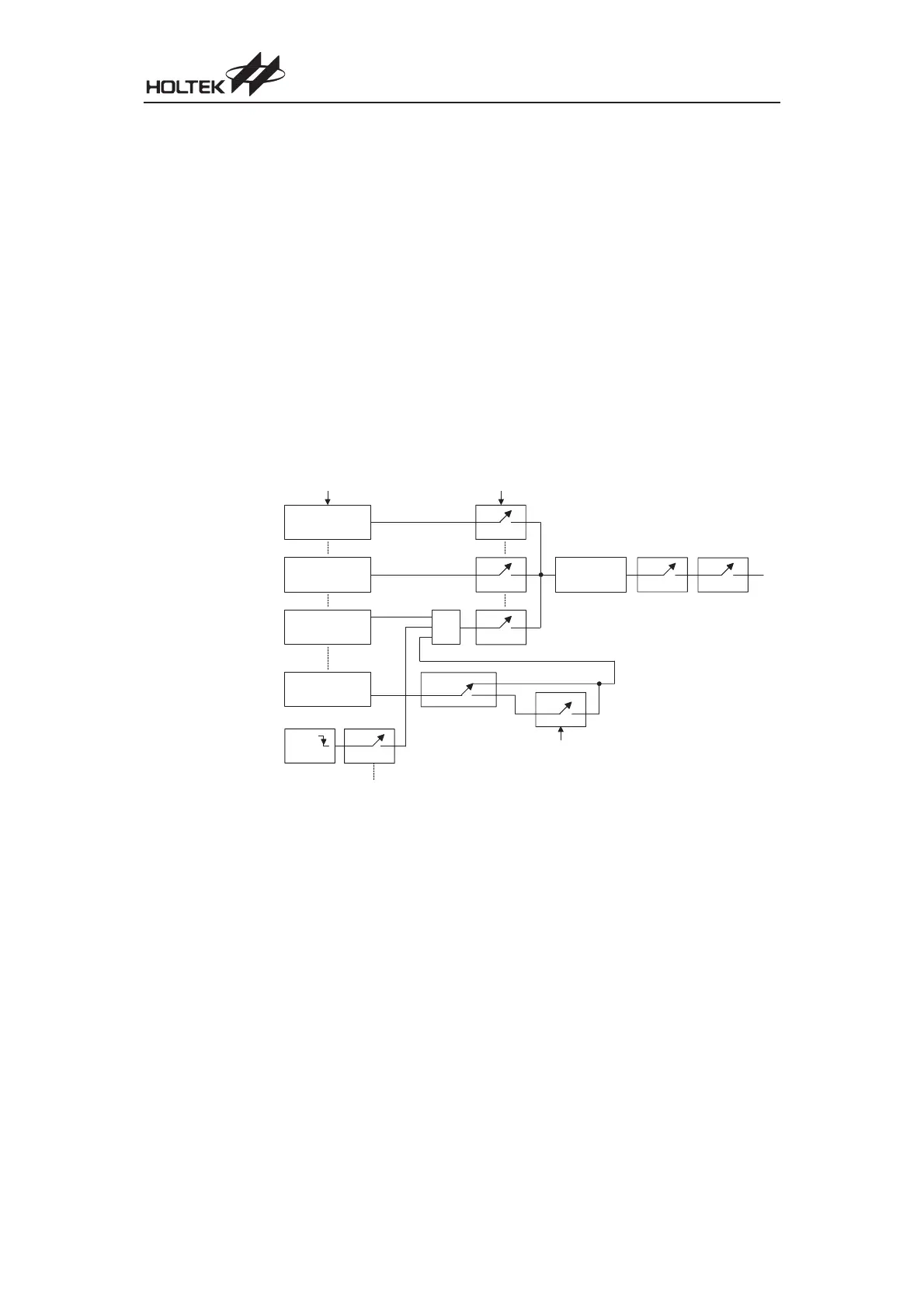
UART Interrupt Scheme
The UART internal function possesses its own internal interrupt and independent interrupt vector.
Several individual UART conditions can generate an internal UART interrupt. These conditions
are, a transmitter data register empty, transmitter idle, receiver data available, receiver overrun,
address detect and an RX pin wake-up. When any of these conditions are created, if the UART in
-
terrupt is enabled and the stack is not full, the program will jump to the UART interrupt vector
where it can be serviced before returning to the main program. Four of these conditions, have a
corresponding USR register flag, which will generate a UART interrupt if its associated interrupt en
-
able flag in the UCR2 register is set. The two transmitter interrupt conditions have their own corre
-
sponding enable bits, while the two receiver interrupt conditions have a shared enable bit. These
enable bits can be used to mask out individual UART interrupt sources.
The address detect condition, which is also a UART interrupt source, does not have an associated
flag, but will generate a UART interrupt when an address detect condition occurs if its function is
enabled by setting the ADDEN bit in the UCR2 register. An RX pin wake-up, which is also a UART
interrupt source, does not have an associated flag, but will generate a UART interrupt if the
microcontroller is woken up by a low going edge on the RX pin, if the WAKE and RIE bits in the
UCR2 register are set. Note that in the event of an RX wake-up interrupt occurring, there will be a
delay of 1024 system clock cycles before the system resumes normal operation.
Note that the USR register flags are read only and cannot be cleared or set by the application pro
-
gram, neither will they be cleared when the program jumps to the corresponding interrupt servic
-
ing routine, as is the case for some of the other interrupts. The flags will be cleared automatically
when certain actions are taken by the UART, the details of which are given in the UART register
section. The overall UART interrupt can be disabled or enabled by the EURI bit in the INTC1 inter
-
rupt control register to prevent a UART interrupt from occurring.
Chapter 1 Hardware Structure
81
U S R R e g i s t e r
T r a n s m i t t e r E m p t y
F l a g T X I F
T r a n s m i t t e r I d l e
F l a g T I D L E
R e c e i v e r D a t a
A v a i l a b l e R X I F
R e c e i v e r O v e r r u n
F l a g O E R R
R X 7 i f B N O = 0
R X 8 i f B N O = 1
A D D E N
0
1
0
1
R X P i n
W a k e - u p
W A K E
0
1
U C R 2 R e g i s t e r
T E I E
T I I E
R I E
U A R T I n t e r r u p t
R e q u e s t F l a g
U R F
E U R I
I N T C 1
R e g i s t e r
E M I
I N T C 0
R e g i s t e r
U C R 2 R e g i s t e r
0
1
0
1
0
1
O R
UART Interrupt Scheme
 Loading...
