6
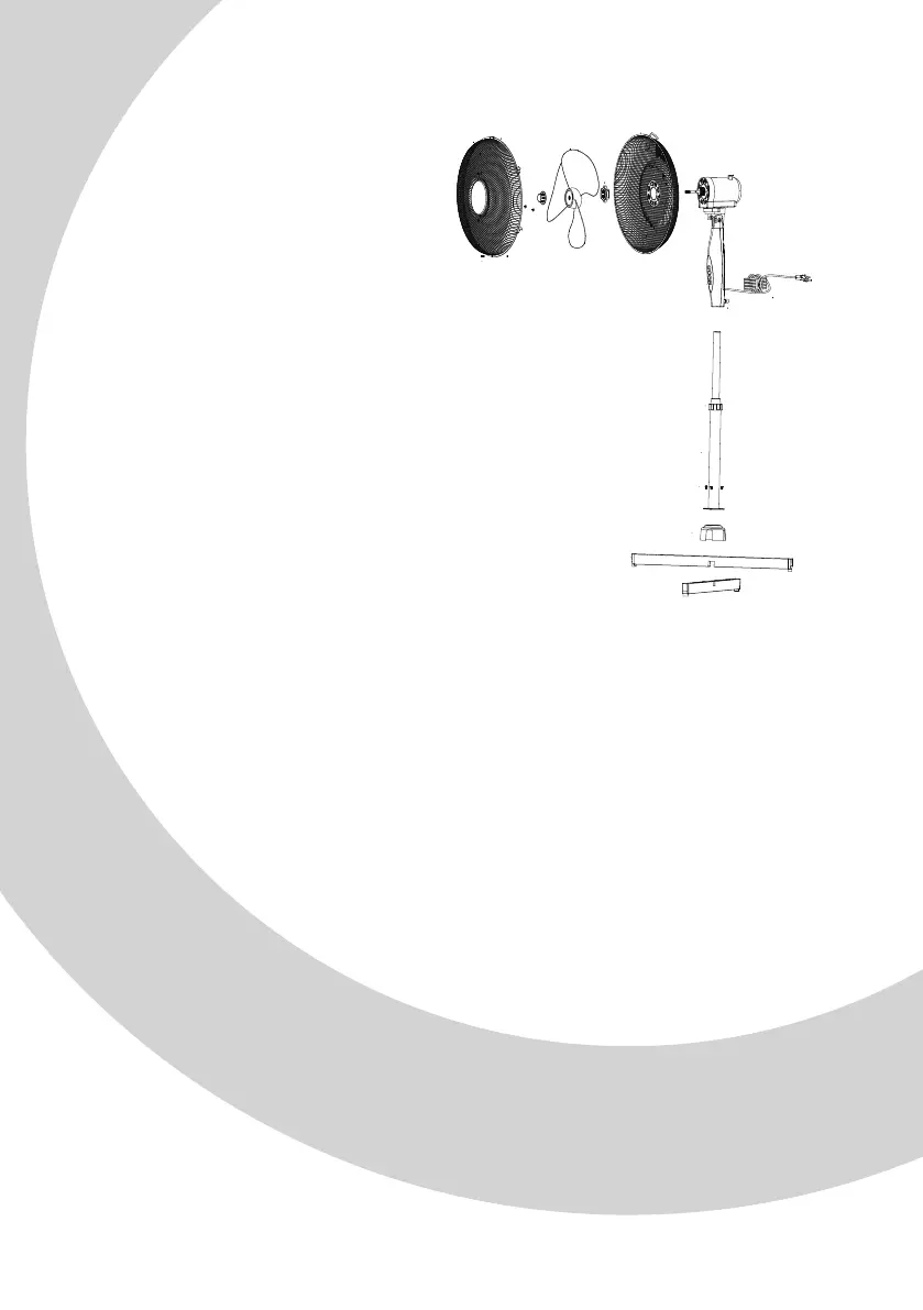
PRODUCT STRUCTURE
4.
BODY ASSEMBLY
Loosen and remove the four screws (04) from the bar
A (13) and bar B (14). Then cross bar A (13) and bar B
(14) so that they interlock. Be sure to align the four
holes in the bars with the outer tube. Tighten the
outer tube to the bars with the four screws.
Loosen and remove the height adjustment control
collar (06) from the top of the inner pipe. Put the base
decorative cap (05) down to the base through the
tube inside.
Replace the height adjustment control collar (06) on
top of the inner pipe (03). Pull the inner pipe (03) out
from the outer tube to adjust the tube to the desired
height and tighten the collar.
Slightly loosen the switch rotate ring (07) by turning it
anti-clockwise. Put the switch box down over the
inner pipe and tighten the switch rotate ring.
Make sure it is tightly secured.
1.
2.
3.
01
02
03
04
05
06
07
08
09
Motor
Oscillation knob
Inner pipe
Screw
Decorative cap
Height adjustment
control collar
Switch rotate ring
Locking nut
Blade cap
Back safety grille
Fan blade
Front safety grille
Bar A
Bar B
Safety screw and nut
[12]
[11]
[09]
[08]
[10]
[03]
[07]
[01]
[06]
[05]
[13]
[14]
[04]
[02]
10
11
12
13
14
15
[15]