3 TO DISARM THE SYSTEM
a. Enter the pass number followed by the DISARM button.
b. You will hear one beep and the ARM icon will disappear from
the Auto-Dialer screen to confirm that the Auto-Dialer has
been DISARMED,
c. You can press and hold "DISARM" button 2 seconds on
remote unit to DISARM main unit.
4 DOOR CHIME ON/OFF
a. Switch the CHIME button to ON, on the side of the
Auto-Dialer.
b. Wait for 60 Seconds, there will be one beep.
c. When movement is detected in the protected area the'DING
DONG' chime will sound.
d. Switch the CHIME button to OFF, on the side of the
Auto-dialer to stop the 'DING DONG' from sounding.
NOTE: When the Auto-dialer is in ARM mode the CHIME will
NOT sound.
5 PANIC BUTTON
a. Press "PANIC" button on main unit or press and hold
"PANIC" button 2 seconds on remote control, instantly the
ALARM will sound for 30 seconds, and the Auto-Dialer will
begin dialling the stored numbers.
b. To stop the alarm and the stored numbers being dialed,
press password then ARM/DISARM button.
c. Or press and hold "DISARM" button 2 seconds on remote
unit to stop the alarm and auto dialer.
PAUSE •
The "PAUSE"
function can be stored as
one digit in the
telephone number memory for some PABX dialling operation
and
every one "PAUSE" in the memory dialling sequence will stop
for 3.6 seconds. For example, if you store telephone number
"7,7,7,5,3,5,5--226"
to memory location 2, operation as follows:
a. Press password
(
0-0-0), then press "PROG" button, the
system will into setup mode,
b. Press PROG button to select function menu "MEMORY" icon flash.
c. Press "ARM/DISARM" button to confirm.
d. The system will get into first telephone number setting and
LCD display.
e. Press "*/UP" or "#IDOWN" to select memory location 2.
f. Press "7,7,7,5,3,5,5"
,
Pause "2,2,6".
g. Press "ARM/DISARM" button to confirm and the LCD will
return display setup menu.
B A T T E R YL
O
W
D •'
^^.ihen the 9V
battery is running
low, the battery low LED will
flash once every 3 seconds to indicate the low battery in ARM
mode.
NOTE:
change to a new alkaline
9V battery immediately, other
wise it may cause the sensor
to not detect properly and may
appear the fault trigger alarm and dialling phenomenon.
-7-
View Trigger Records
In standby mode, press "#/DOWN" to view last 5 trigger
records.
View store
telephone numbers
In standby mode, press "*/UP" to view stored telephone number.
NOTE: not press any button 10 seconds system will
automatically exit view mode.
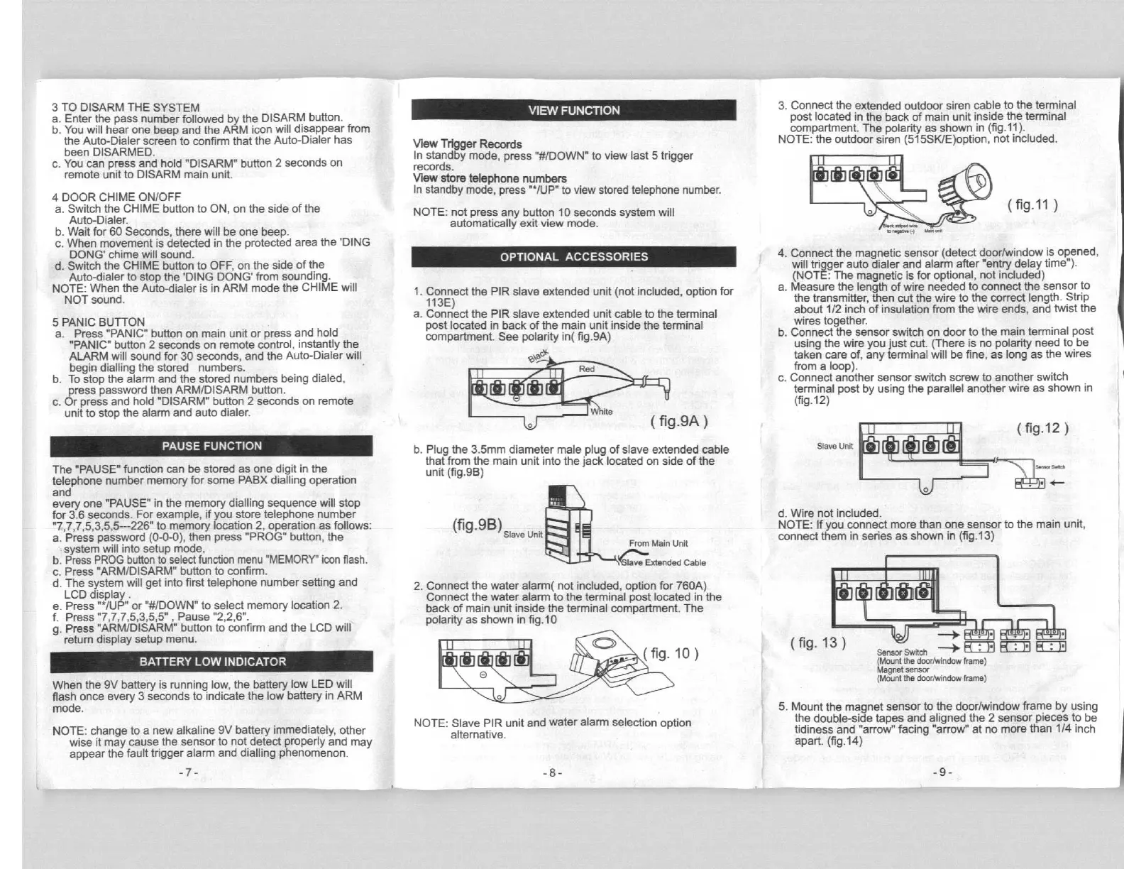
1. Connect the PIR slave extended unit (not included, option for
113E)
a. Connect the PIR slave extended unit cable to the terminal
post located in back of the main unit inside the terminal
compartment. See polarity in( fig.9A)
\aG*
Red
ite
(fig.9A)
b. Plug the 3.5mm diameter male plug of slave extended cable
that from the main unit into the jack located on side of the
unit (fig.9B)
(fig.9B)
Slave Unit
From Main untt
lave Extended Cable
2. Connect the water alarm( not included, option for 760A)
Connect the water alarm to the terminal post located in the
back of main unit inside the terminal compartment. The
polarity as shown in fig.10
(fig.10)
NOTE: Slave PIR unit
and water alarm selection option
alternative.
-8-
3. Connect the extended outdoor siren cable to the terminal
post located in the back of main unit inside the terminal
compartment. The polarity as shown in (fig.11).
NOTE: the outdoor siren (515SK/E)option, not included.
o ( fg-11
..^,".
4. Connect the magnetic sensor (detect door/window is opened,
will trigger auto dialer and alarm after "entry delay time").
(NOTE: The magnetic is for optional, not included)
a. Measure the length of wire needed to connect the sensor to
the transmitter, then cut the wire to the correct length. Strip
about 1/2 inch of insulation from the wire ends, and twist the
wires together.
b. Connect the sensor switch on door to the main terminal post
using the wire you just cut. (There is no polarity need to be
taken care of, any terminal will be fine, as long as the wires
from a loop).
c. Connect another sensor switch screw to another switch
terminal post by using the parallel another wire as shown in
(fig.12)
11
( fig.12 )
Slave Unit 9
4
^--
0
d. Wire not included.
NOTE: If you
connect more than one sensor to the main unit,
connect them in series as shown in
(fig.13)
l[Ull
F^93
91
q^m
^^^
(fig.13 ___+
Sensor Switch
(Mount the doorlwindow frame)
Magnet sensor
(Mount the doorlwindow frame)
5. Mount the magnet sensor to the door/window frame by using
the double-side tapes
and aligned
the 2 sensor pieces to be
tidiness and "arrow" facing "arrow" at no more than 114 inch
apart. (fig.14)
9-


 To Next Page
 Loading...