8
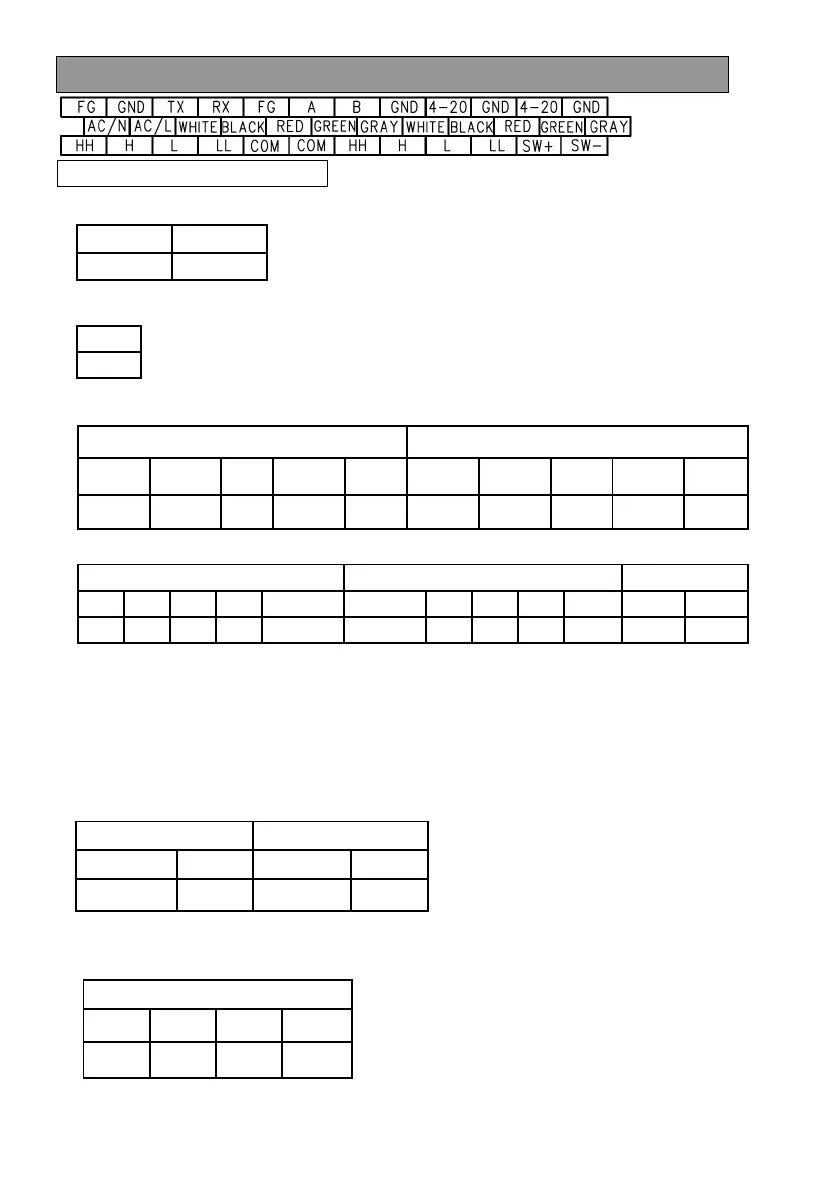
Wiring
Explanation of the terminal
1) Connect the power supply, 100 - 240VAC.
2) Connect FG terminal to ground.
3) Connect the ultrasonic sensor to CH1 or CH2.
CH1 CH2
WHITE
BLACK
RED
GREEN
GRAY
WHITE
BLACK
RED
GREEN
GRAY
B3 B4 B5
B6 B7
B8 B9 B10
B11
B12
4) Wirings for ALARM
CH1 ALARM CH2 ALARM
PULSE OUT
HH
H
L
LL
COMMON COMMON
HH
H
L
LL SW+
SW-
C1
C2
C3
C4
C5 C6 C7
C8
C9
C10
C11
C12
HH and COMMON are short-circuited by relay.
H and COMMON, L-COMMON, LL-COMMON are short-circuited in the same
manner.
[Caution] Provide the surge protection in case the induced load is driven.
5) Wirings for 4-20mA output
A11 and A12 are used for the output of the level difference between CH1 and CH2.
6) Wirings for RS-485
Use the shielded twisted pair cable for RS-485 line. Connect the shield to FG, A5.
AC/N AC/L
B1 B2
F.G.
A1
CH1 CH2
4-20mA
GND
4-20mA
GND
A9 A10 A11 A12
RS485
F.G.
A(+)
B(-)
GND
A5 A6 A7 A8
 Loading...