Do you have a question about the Honda CB250K3 and is the answer not in the manual?
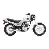
Specifications for overall length, width, height, wheelbase, and ground clearance for various models.
Details on frame type, suspension, tire size, and brake specifications.
Engine type, cylinder arrangement, bore, stroke, compression, and torque specifications.
Specifications for clutch, transmission, gear ratios, and final reduction.
Comprehensive list of specialized tools for CB/CL250, 350 models with reference numbers and usage.
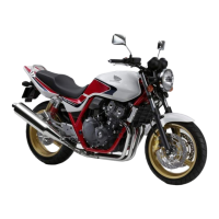
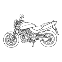
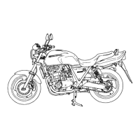
Comparison of modifications across different models (CB250, CL250, SL350) for various years.
Key features of the engine, including camshaft, rocker arms, and valve clearance.
Details on the power transmission sequence, including clutch, gears, and drive sprocket.
Step-by-step instructions for safely removing the engine from the motorcycle frame.
Instructions for reassembling the engine back onto the motorcycle frame.
Explanation of the valve mechanism, including camshaft, rocker arms, and valve operation.
Procedure for disassembling the valve mechanism components.
Guidelines for inspecting valve components for wear and proper function.
Steps for reassembling the valve mechanism components correctly.
Description of pistons and cylinders, including materials and design features.
Procedure for disassembling the piston and cylinder assembly.
Methods for inspecting cylinder bore, piston, and taper.
Instructions for reassembling pistons and cylinders.
Explanation of the hydraulic cam chain tensioner's function and operation.
Steps for disassembling the cam chain tensioner assembly.
Procedure for inspecting the cam chain tensioner for wear or damage.
Instructions for reassembling the cam chain tensioner.
Overview of the pressure-feed lubrication system and its oil circuits.
Steps for disassembling the lubrication system components, including the oil pump and clutch.
Procedures for inspecting the oil filter, crankcase, and oil pump.
Instructions for reassembling the lubrication system components.
Explanation of the clutch operation, components, and power transmission.
Procedure for disassembling the clutch assembly.
Methods for inspecting and adjusting clutch components.
Steps for reassembling the clutch assembly.
Description of the crankshaft and connecting rods, materials, and construction.
Procedure for disassembling the crankshaft and connecting rod components.
Methods for inspecting crankshaft and connecting rod for wear and alignment.
Instructions for reassembling the crankshaft and connecting rod.
Explanation of the transmission system, including its five-speed constant-mesh design.
Procedure for disassembling the transmission components.
Methods for inspecting transmission components like backlash and gear wear.
Instructions for reassembling the transmission components.
Explanation of the gear shift mechanism, including linkage and pedal operation.
Procedure for disassembling the gear shift mechanism.
Methods for inspecting gear shift forks and bore.
Instructions for reassembling the gear shift mechanism.
Description of the kick starter mechanism and its operation.
Procedure for disassembling the kick starter assembly.
Inspection of kick starter components for wear.
Instructions for reassembling the kick starter components.
Description of crankcase materials and construction, including oil flow.
Procedure for disassembling the crankcase assembly.
Inspection of crankcases for damage and oil leaks.
Instructions for reassembling the crankcase.
Description of the CV carburetor, its features, and construction.
Procedure for disassembling the carburetor components.
Inspection of carburetor settings, idle, and throttle adjustments.
Description of the handlebar, its mounting, and design for rider comfort.
Description of the fork top bridge and its mounting to the steering stem.
Description of the front fork's hydraulic telescopic system and damping action.
Description of the steering stem, its mounting, and function.
Description of the fuel tank, its mounting, and fuel cap.
Procedure for disassembling the fuel tank assembly.
Inspection of the fuel tank for leaks and damage.
Instructions for reassembling the fuel tank assembly.
Description of the frame body, its semi-cradle, double-cradle construction, and mounting points.
Procedure for disassembling the frame body components.
Inspection of frame welds for cracks or damage.
Instructions for reassembling the frame body.
Description of the seat, its construction, and features for rider comfort.
Procedure for disassembling the main stand.
Description of the dual exhaust system and mufflers.
Procedure for disassembling the exhaust pipes and mufflers.
Inspection of the muffler for damage.
Instructions for reassembling the exhaust pipes and mufflers.
Description of the twin air cleaners for each carburetor.
Procedure for removing the air cleaner cover and element.
Inspection of the air cleaner element for dust and damage.
Instructions for reassembling the air cleaner components.
Description of the rear fork and fender construction.
Procedure for disassembling the rear fork assembly.
Instructions for reassembling the rear fork assembly.
Description of the De Carbon type rear cushion damper.
Explanation of the rear cushion's operation and damping adjustment.
Description of the double-tube rear shock absorber and its damping mechanism.
Procedure for disassembling the rear cushion assembly.
Inspection of the rear cushion spring and damper for wear and leaks.
Instructions for reassembling the rear cushion assembly.
Description of the front wheel, its components, and mounting.
Recommended tire brands, sizes, and air pressure for the SL350.
Steps for assembling the front wheel components.
Instructions for reassembling the front wheel after maintenance.
Detailed procedures for the front wheel assembly, specifically for models with disc brakes.
Procedure for disassembling brake calipers and master cylinder.
Procedures for inspecting brake calipers and master cylinder for wear and damage.
Steps for assembling the brake calipers and master cylinder.
Procedure for adjusting the disc brake system after assembly.
Description of the rear wheel, its components, and differences from the front wheel.
Procedure for disassembling the rear wheel assembly.
Inspection of rear wheel components like runout, axle bend, and brake drum.
Instructions for reassembling the rear wheel components.
Description, removal, inspection, and reassembly of the ignition coil.
Details on spark plug types, inspection, and installation.
Description, removal, inspection, and reinstallation of the noise suppressor.
Description, disassembly, inspection, and reassembly of the AC generator.
Description, disassembly, inspection, and reassembly of the rectifying system.
Description, removal, inspection, and charging procedures for the battery.
Description, disassembly, inspection, and reassembly of the starting motor and related components.
Description, removal, inspection, and reassembly of the ignition switch.
Description, removal, and inspection of the stoplight switch.
Description, removal, reassembly, and inspection of starter and lighting switches.
Description, disassembly, inspection, and reassembly of turn signal and horn control switches.
Description, inspection, removal, and reassembly of the neutral switch.
Description of the wiring harness and wire lead colors for identification.
Procedure for removing the wiring harness from the motorcycle.
Inspection of wiring harness for abrasions, breaks, and secure connections.
Instructions for reassembling the wiring harness.
General overview of the SL350 engine, including kick mechanism and disassembly.
Step-by-step instructions for removing the engine from the SL350 motorcycle.
Instructions for reassembling the engine back onto the motorcycle frame.
Procedure for disassembling the primary kick starter components.
Inspection of kick starter gear teeth and spindle for wear.
Instructions for reassembling the kick starter components.
Carburetor specifications for the SL350 model, including jet sizes and float height.
Explanation of carburetor circuits: starting, low-speed, main circuit, and float circuits.
Description of the handlebar design and its mounting on the CL250/350.
Description of the fork top bridge and its mounting to the steering stem.
Description of the front fork's piston valve type suspension system.
Disassembly, inspection, and assembly procedures for free valve type front forks.
Description of the steering stem, its mounting, and function for stability.
Procedure for disassembling the steering stem assembly.
Inspection of the steering stem for bends or damage.
Instructions for reassembling the steering stem.
| Displacement | 249 cc |
|---|---|
| Fuel System | Carburetor |
| Transmission | 5-speed |
| Final Drive | Chain |
| Front Suspension | Telescopic fork |
| Front Brake | Single disc |
| Rear Brake | Drum |
| Front Tire | 3.00-18 |
| Rear Tire | 3.50-18 |
| Fuel Capacity | 12 liters |
| Engine Type | Four-stroke |
| Rear Suspension | Swingarm |
| Height | 1, 070 mm |
| Seat Height | 780 mm |
| Weight | 145 kg |