EasyManua.ls Logo

Honda CQ-EH8160AK User Manual

Honda CQ-EH8160AK
37 pages
To Next Page IconTo Next Page
Page #1 background imageLoading...
Page #1 background image
General
Power Supply DC 12V (11V - 16V),
Test Voltage 13.2V
Negative Ground
Current Consumption Less than 3.0A (at 0.5W)
Power Output 30W×4
Output Impedance 4
AM Radio
Frequency Range 530 - 1,710kHz
Usable Sensitivity 24dB/µV (S/N 20dB)
FM Stereo Radio
Frequency Range 87.7 - 107.9MHz
Usable Sensitivity 6dB/µV (S/N 30dB)
Cassette Player
Reproduction System 4-Track, 2-Program Stereo
Tape Speed 4.76cm/sec.
HONDA
CQ-EH8160AK
AM/FM MPX ELECTRONIC TUNING
RADIO with Stereo Cassette Tape
Player and 6-Disc CD Changer
HONDA PART No. : 39100-S9A-A200
ID CORD : 1TN0
VEHICLE : CR-V
DESTINATION : North America
PRODUCED AFTER : Feb., 2002
Wow and Flutter Less than 0.2% (WRMS)
Signal to Noise Ratio More than 38dB (IHF-A)
IDC
Signal to Noise Ratio More than 63dB (IHF-A)
Total Harmonic Distortion Less than 0.4%
Channel Separation More than 50dB (IHF-A)
Dimensions** (W×H×D) 180×102×170mm
Weight** 2.4kg
* Specifications and the design are subject to possible modification
without notice due to improvements.
** Dimensions and Weight shown are approximate.
Dolby noise reduction manufactured under license from Dolby
Laboratories Licensing Corporation.
“Dolby” and the double-D symbol
are trade marks of Dolby
Laboratories Licensing Corporation.
AUTOMOTIVE ELECTRONICS
Specification*
ORDER No.0159
I0
Question and Answer IconNeed help?

Do you have a question about the Honda CQ-EH8160AK and is the answer not in the manual?

Honda CQ-EH8160AK Specifications

General IconGeneral
ModelCQ-EH8160AK
CategoryCar Stereo System
Channels4
CD PlayerYes
MP3 PlaybackYes
WMA PlaybackYes
AAC PlaybackNo
USB PortYes
Auxiliary InputYes
BluetoothNo
DisplayLCD
CompatibilityHonda vehicles
Supported FormatsCD-R/CD-RW

Summary

Specification*

6 BLOCK DIAGRAM (Main, Display, Tape Block)

7 BLOCK DIAGRAM (CD Servo Block)

8 TERMINALS DESCRIPTION

8.1. Main Block

Description of terminals for the main control unit.

8.3. CD Servo Block

Description of terminals for the CD servo control unit.

9 ALIGNMENT INSTRUCTIONS

9.1. Alignment Conditions

Conditions required for performing unit adjustments and calibrations.

9.2. Dolby NR Alignment

Specific steps for aligning Dolby noise reduction.

12 PACKAGE AND IC BLOCK DIAGRAM

13 REPLACEMENT PARTS LIST

14 EXPLODED VIEW (Unit)

15 CD CHANGER PARTS LIST

16 EXPLODED VIEW (CD Deck-1)

17 EXPLODED VIEW (CD Deck-2)

18 EXPLODED VIEW (CD Deck-3)

19 TAPE PLAYER PARTS

19.1. IC's and Transistors

List of integrated circuits and transistors for the tape player.

20 EXPLODED VIEW (Tape Deck)

22 SCHEMATIC DIAGRAM (1)

22.1. Tape Block

Schematic diagram for the tape playback circuitry.
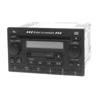
23 SCHEMATIC DIAGRAM (2)

23.4. CD Servo Block

Related product manuals