EasyManua.ls Logo

Honda GX270H User Manual

Honda GX270H
182 pages
To Next Page IconTo Next Page
Page #1 background imageLoading...
Page #1 background image
0-1
dummyheaddummyhead
How to use this manual
How to use thi s manual
A Few Words About Safety
SERVICE INFORMATION
The service and repair information contained in this manual is intended for use by qualified, professional technicians. Attempting
service or repairs without the proper training, tools, and equipment could cause injury to you and/or others. It could also damage
this Honda product or create an unsafe condition.
This manual describes the proper methods and procedures for performing service, maintenance, and repairs. Some procedures
require the use special tools. Any person who intends to use a replacement part, service procedure, or a tool that is not
recommended by Honda must determine the risks to their personal safety and the safe operation of this product.
If you need to replace a part, use Honda Genuine parts with the correct part number or an equivalent part. We strongly recommend
that you do not use replacement parts of inferior quality.
For Your Customer’s Safety
Proper service and maintenance are essential to the customer’s safety and the reliability of this product. Any error or oversight
while servicing this product can result in faulty operation, damage to the product, or injury to others.
For Your Safety
Because this manual is intended for the professional service technician, we do not provide warnings about many basic shop safety
practices (e.g., Hot parts-wear gloves). If you have not received shop safety training or do not feel confident about your knowledge
of safe servicing practices, we recommend that you do not attempt to perform the procedures described in this manual.
Some of the most important general service safety precautions are given below. However, we cannot warn you of every
conceivable hazard that can arise in performing service and repair procedures. Only you can decide whether or not you should
perform a given task.
Important Safety Precautions
Make sure you have a clear understanding of all basic shop safety practices and that you are wearing appropriate clothing and
using safety equipment. When performing any service task, be especially careful of the following:
Read all of the instructions before you begin, and make sure you have the tools, the replacement or repair parts, and the skills
required to perform the tasks safely and completely.
Protect your eyes by using proper safety glasses, goggles, or face shields anytime you hammer, drill, grind, or work around
pressurized air, pressurized liquids, springs or other stored-energy components. If there is any doubt, put on eye protection.
Use other protective wear when necessary, for example gloves or safety shoes. Handling hot or sharp parts can cause severe
burns or cuts. Before you grab something that looks like it can hurt you, stop and put on gloves.
Protect yourself and others whenever you have equipment hoisted up in the air. Anytime you lift this product with a hoist, make
sure that the hoist hook is securely attached to the product.
Make sure the engine is off before you begin any servicing procedures, unless the instruction tells you to do otherwise. This will
help eliminate several potential hazards:
Carbon monoxide poisoning from engine exhaust. Be sure there is adequate ventilation whenever you run the engine.
Burns from hot parts. Let the engine and exhaust system cool before working in those areas.
Injury from moving parts. If the instruction tells you to run the engine, be sure your hands, fingers, and clothing are out of the
way.
Gasoline vapors and hydrogen gasses from batteries are explosive. To reduce the possibility of a fire or explosion, be careful when
working around gasoline or batteries.
Use only a nonflammable solvent, not gasoline, to clean parts.
Never store gasoline in an open container.
Keep all cigarettes, sparks, and flames away from the battery and all fuel-related parts.
Improper service or repairs can create an unsafe
condition that can cause your customer or others to
be seriously hurt or killed.
Follow the procedures and precautions in this
manual and other service materials carefully.
Failure to properly follow instructions and
precautions can cause you to be seriously hurt or
killed.
Follow the procedures and precautions in this
manual carefully.
62Z7B000.book 1 ページ 2012年9月27日 木曜日 午前10時21分

Table of Contents

Question and Answer IconNeed help?

Do you have a question about the Honda GX270H and is the answer not in the manual?

Honda GX270H Specifications

General IconGeneral
BrandHonda
ModelGX270H
CategoryEngine
LanguageEnglish

Summary

How to Use This Manual

A Few Words About Safety

Discusses safety information and precautions for service and repair.

Important Safety Precautions

General safety practices for service tasks, including protective wear and equipment.

How to Use This Manual

INTRODUCTION

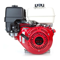
Covers service and repair procedures for Honda GX270H/390H1 engines.

SAFETY MESSAGES

Highlights the importance of safety messages and symbols (DANGER, WARNING, CAUTION).

How to Use This Manual

SERVICE RULES

Guidelines for using Honda Genuine parts, tools, and lubricants.

SYMBOLS

Explains symbols used in the manual for specific service procedures.

1. SPECIFICATIONS

ENGINE SPECIFICATIONS

Lists key engine specifications like displacement, bore, stroke, and power.

PERFORMANCE CURVES

Graphical representation of engine performance data (torque and power).

DIMENSIONAL DRAWINGS

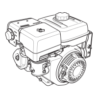
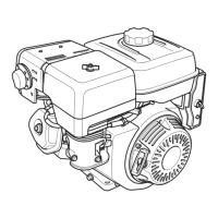
Technical drawings showing engine dimensions and component layouts.

2. SERVICE INFORMATION

MAINTENANCE STANDARDS

Specifies standard and service limit values for engine parts and their measurements.

TORQUE VALUES

Lists recommended torque values for various engine bolts and nuts.

LUBRICATION & SEAL POINT

Details lubrication points and recommended sealants or oils for engine assembly.

TOOLS

Lists specialized tools required for servicing the engine and its components.

HARNESS AND TUBE ROUTING

Illustrates the correct routing of electrical harnesses and fuel/breather tubes.

3. MAINTENANCE

MAINTENANCE SCHEDULE

Outlines the recommended service intervals for regular maintenance items.

ENGINE OIL LEVEL CHECK/CHANGE

Procedure for checking and changing the engine oil level.

REDUCTION CASE OIL LEVEL CHECK/ CHANGE

Procedure for checking and changing the reduction case oil level.

AIR CLEANER CHECK/CLEANING/ REPLACEMENT

Steps for inspecting, cleaning, or replacing the air cleaner element.

SPARK PLUG CHECK/ADJUSTMENT

Guide for inspecting and adjusting the spark plug gap.

SPARK PLUG REPLACEMENT

Procedure for removing and installing a new spark plug.

VALVE CLEARANCE CHECK/ ADJUSTMENT

Procedure for checking and adjusting valve clearances.

4. TROUBLESHOOTING

BEFORE TROUBLESHOOTING

Preliminary checks and advice before starting troubleshooting.

TROUBLESHOOTING HARD STARTING

Diagnostic flow chart for hard starting engine problems.

ENGINE SPEED DOES NOT INCREASE OR STABILIZE

Troubleshooting guide for engine speed problems.

ENGINE DOES NOT STOP WHEN COMBINATION/ ENGINE STOP SWITCH IS TURNED OFF

Troubleshooting steps for when the engine fails to stop.

5. COVER

FAN COVER REMOVAL/INSTALLATION

Procedure for removing and installing the engine's fan cover.

6. FUEL SYSTEM

FUEL TANK REMOVAL/INSTALLATION

Procedure for removing and installing the fuel tank.

AIR CLEANER REMOVAL/ INSTALLATION

Steps for removing and installing the air cleaner assembly.

CARBURETOR REMOVAL/ INSTALLATION

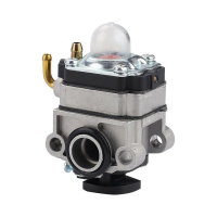
Procedure for removing and installing the carburetor.

CARBURETOR DISASSEMBLY/ ASSEMBLY

Detailed steps for disassembling and assembling the carburetor.

CARBURETOR BODY CLEANING

Instructions for cleaning the carburetor body and its passages.

CARBURETOR INSPECTION

Steps for inspecting the carburetor, including float level.

7. GOVERNOR SYSTEM

GOVERNOR ARM/CONTROL BASE ASSY. REMOVAL/INSTALLATION

Procedure for removing and installing the governor arm and control base assembly.

MAXIMUM SPEED ADJUSTMENT

Guide for adjusting the engine's maximum speed setting.

GOVERNOR ARM/CONTROL BASE ASSY. REMOVAL/INSTALLATION MANUAL OPERATION TYPE

Steps for removing/installing governor parts for manual operation.

EXCEPT MANUAL OPERATION TYPE

Governor system service for types other than manual operation.

MAXIMUM SPEED ADJUSTMENT MANUAL CONTROL TYPE

Procedure for adjusting maximum speed on manual control type engines.

8. CHARGING SYSTEM

SYSTEM DIAGRAM

Electrical diagram of the charging system components.

TROUBLESHOOTING

Diagnostic flow chart for charging system problems.

COOLING FAN/FLYWHEEL REMOVAL/ INSTALLATION

Procedure for removing and installing the cooling fan and flywheel.

CHARGE/LAMP COIL (IF EQUIPPED) REMOVAL/INSTALLATION

Steps for removing and installing the charge/lamp coil.

CHARGE/LAMP COIL INSPECTION

Procedure for inspecting the charge/lamp coil's electrical properties.

9. IGNITION SYSTEM

SYSTEM DIAGRAM

Electrical diagram of the ignition system.

TROUBLESHOOTING

Diagnostic guide for ignition system problems.

IGNITION COIL REMOVAL/ INSTALLATION

Procedure for removing and installing the ignition coil.

IGNITION COIL AIR GAP CHECK/ ADJUSTMENT

Steps for checking and adjusting the ignition coil air gap.

SPARK TEST

Procedure for testing for spark at the spark plug.

IGNITION COIL INSPECTION

Procedure for inspecting the ignition coil's primary and secondary resistance.

10. STARTING SYSTEM

SYSTEM DIAGRAM

Electrical diagram of the starting system.

TROUBLESHOOTING

Diagnostic guide for starting system problems.

RECOIL STARTER REMOVAL/ INSTALLATION

Procedure for removing and installing the recoil starter.

RECOIL STARTER Assy. DISASSEMBLY/ ASSEMBLY

Detailed steps for disassembling and assembling the recoil starter.

RECOIL STARTER INSPECTION

Procedures for inspecting recoil starter operation and pulley.

STARTER MOTOR REMOVAL/ INSTALLATION

Steps for removing and installing the starter motor.

STARTER MOTOR DISASSEMBLY/ ASSEMBLY

Detailed procedure for disassembling and assembling the starter motor.

STARTER MOTOR INSPECTION

Procedures for inspecting starter motor performance and brush length.

11. OTHER ELECTRICAL

COMPONENT LOCATION

Identifies the location of electrical components on the engine.

CONTROL BOX REMOVAL/ INSTALLATION

Procedure for removing and installing the control box.

CONTROL BOX DISASSEMBLY/ ASSEMBLY

Detailed steps for disassembling and assembling the control box.

OIL LEVEL SWITCH INSPECTION

Procedure for inspecting the oil level switch for continuity.

ENGINE STOP SWITCH INSPECTION

Procedure for inspecting the engine stop switch's continuity.

COMBINATION SWITCH INSPECTION

Procedure for inspecting the combination switch's continuity.

SILICON RECTIFIER INSPECTION

Procedure for inspecting the silicon rectifier's continuity.

CIRCUIT PROTECTOR INSPECTION

Procedure for inspecting the circuit protector's continuity.

12. MUFFLER

MUFFLER REMOVAL/INSTALLATION

Procedure for removing and installing the muffler assembly.

MUFFLER REMOVAL/INSTALLATION SOLID PROTECTOR TYPE

Steps for removing and installing the muffler with solid protector.

MUFFLER REMOVAL/INSTALLATION INNER/OUTER PROTECTOR TYPE

Procedure for removing and installing the muffler with inner/outer protectors.

13. CYLINDER HEAD/VALVES

CYLINDER HEAD REMOVAL/ INSTALLATION

Procedure for removing and installing the cylinder head assembly.

CYLINDER HEAD DISASSEMBLY/ ASSEMBLY

Detailed steps for disassembling and assembling the cylinder head.

CYLINDER HEAD/VALVES INSPECTION

Procedures for inspecting cylinder head and valve components.

VALVE SEAT RECONDITIONING

Steps for reconditioning valve seats.

CYLINDER HEAD REMOVAL/ INSTALLATION

Detailed procedure for removing and installing the cylinder head, including torque specs.

CYLINDER COMPRESSION CHECK

Procedure for measuring cylinder compression using a gauge.

CYLINDER HEAD WARPAGE

How to check for cylinder head warpage using measurement tools.

VALVE SEAT WIDTH

Procedure for measuring and reconditioning valve seat width.

VALVE STEM O.D.

Procedure for measuring valve stem outer diameter and checking for wear.

GUIDE-TO-STEM CLEARANCE

How to calculate and check valve guide-to-stem clearance.

VALVE SPRING FREE LENGTH

Procedure for measuring valve spring free length and checking against limits.

VALVE SEAT RECONDITIONING

Procedure for cleaning, marking, and reconditioning valve seats.

14. CRANKCASE

CRANKCASE COVER REMOVAL/ INSTALLATION

Procedure for removing and installing the crankcase cover.

CRANKSHAFT/BALANCER/PISTON REMOVAL/INSTALLATION

Steps for removing and installing crankshaft, balancer, and piston assemblies.

REDUCTION UNIT DISASSEMBLY/ ASSEMBLY

Steps for disassembling and assembling the reduction unit.

GOVERNOR DISASSEMBLY/ ASSEMBLY

Steps for disassembling and assembling the governor mechanism.

PISTON DISASSEMBLY/ASSEMBLY

Detailed procedure for disassembling and assembling the piston.

CRANKCASE COVER/CYLINDER BARREL/PISTON/CONNECTING ROD/CRANKSHAFT/CAMSHAFT INSPECTION

Inspection procedures for various engine internal components.

REDUCTION UNIT INSPECTION

Inspection procedures for reduction unit components.

CRANKSHAFT/BALANCER WEIGHT BEARING/OIL SEAL REPLACEMENT (CRANKCASE COVER SIDE)

Procedure for replacing bearings and oil seals on the crankcase cover side.

CRANKSHAFT BEARING REPLACEMENT (FLYWHEEL SIDE)

Steps for replacing crankshaft bearings on the flywheel side.

GX270H CRANKSHAFT OIL SEAL REPLACEMENT (CYLINDER BARREL SIDE)

Procedure for replacing GX270H crankshaft oil seal on the cylinder barrel side.

GX390H1 BALANCER WEIGHT BEARING/GOVERNOR ARM SHAFT OIL SEAL/CRANKSHAFT OIL SEAL REPLACEMENT (CYLINDER BARREL SIDE)

Procedure for replacing bearings and oil seals on GX390H1 cylinder barrel side.

GX270H CRANKSHAFT/P.T.O.SHAFT OIL SEAL REPLACEMENT (1/2 REDUCTION CLUTCH TYPE)

Procedure for replacing GX270H PTO shaft oil seals on 1/2 reduction clutch type.

GX390H1 COUNTERSHAFT/P.T.O. SHAFT BEARING/OIL SEAL REPLACEMENT (1/6 REDUCTION GEAR TYPE)

Procedure for replacing GX390H1 shaft bearings/oil seals on 1/6 reduction gear type.

GX270H COUNTERSHAFT/P.T.O. SHAFT BEARING REPLACEMENT (CRANKCASE COVER SIDE)

Procedure for replacing GX270H shaft bearings on crankcase cover side.

GX390H1 COUNTERSHAFT/P.T.O. SHAFT BEARING REPLACEMENT (CRANKCASE COVER SIDE)

Procedure for replacing GX390H1 shaft bearings on crankcase cover side.

CRANKSHAFT/BALANCER/PISTON REMOVAL/INSTALLATION

Detailed steps for removing and installing crankshaft, balancer, and piston.

PISTON DISASSEMBLY/ASSEMBLY

Detailed procedure for disassembling and assembling the piston, rings, and pin.

CRANKCASE COVER/CYLINDER BARREL/PISTON/CONNECTING ROD/CRANKSHAFT/CAMSHAFT INSPECTION

Inspection procedures for various engine internal components.

REDUCTION UNIT INSPECTION

Inspection procedures for reduction unit components.

PISTON SKIRT O.D.

Procedure for measuring piston skirt outside diameter.

PISTON-TO-CYLINDER CLEARANCE

How to calculate and check piston-to-cylinder clearance.

PISTON RING SIDE CLEARANCE

Procedure for measuring piston ring side clearance.

CONNECTING ROD BIG END SIDE CLEARANCE

How to measure connecting rod big end clearance.

CONNECTING ROD SMALL END I.D.

Procedure for measuring connecting rod small end inside diameter.

CONNECTING ROD BIG END I.D.

Procedure for measuring connecting rod big end inside diameter.

CRANKPIN O.D.

Procedure for measuring crankpin outside diameter.

CONNECTING ROD BIG END OIL CLEARANCE

Procedure for measuring connecting rod big end oil clearance using plastigauge.

CRANKSHAFT RUNOUT

How to measure crankshaft runout using a dial indicator.

CAMSHAFT CAM HEIGHT

Procedure for measuring camshaft cam height.

CAMSHAFT O.D.

Procedure for measuring camshaft outside diameter.

15. WIRING DIAGRAMS

HOW TO READ A WIRING DIAGRAM & RELATED INFORMATION

Guide on understanding wiring diagrams, connectors, and symbols.

WIRING DIAGRAMS

Contains actual wiring diagrams for the system.

HOW TO READ WIRING DIAGRAM

Detailed guide on reading wiring diagrams, including symbol meanings and terminal identification.

WIRING DIAGRAMS NO CHARGE COIL TYPE

Wiring diagram for models without a charge coil.

WIRING DIAGRAMS 1 A/3 A CHARGE COIL TYPE

Wiring diagram for models with 1 A/3 A charge coils.

Related product manuals