Do you have a question about the Honda HRR216VKA K5 and is the answer not in the manual?
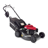
| Engine | Honda GCV160 |
|---|---|
| Engine Displacement | 160cc |
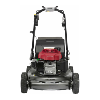
| Cutting Width | 21 inches |
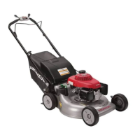
| Cutting Height Adjustment | 6 positions |
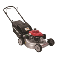
| Drive Type | Self-propelled |
| Starter | Recoil |
| Deck Material | Steel |
| Fuel Capacity | 0.25 gallons |
| Weight | 84 lbs |
| Mulching Capability | Yes |
| Warranty | 3 years |
General guidelines for performing service and repairs.
Importance of proper service for customer safety and product reliability.
Basic safety precautions for technicians performing service.
Critical safety practices and precautions to follow before and during service.
Explanation of safety symbols and signal words used in the manual.
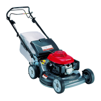
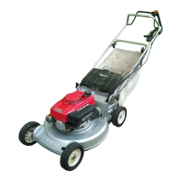
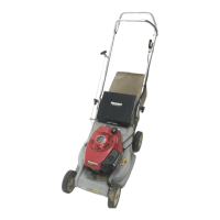
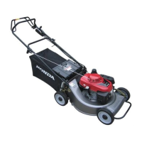
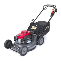
Guide to identifying different versions of the lawn mower based on serial numbers.
Technical specifications for mower dimensions, weights, and fluid capacities.
Detailed specifications for the mower's engine components and performance.
Specifications related to the mower's drive system, including type and lubrication.
Overview of features available across different mower versions.
Essential rules and guidelines to follow when performing service on the mower.
Explanation of symbols and their meanings within the manual.
Information on where to find engine and frame serial numbers.
Detailed service specifications for various mower parts and systems.
Specific torque values for fasteners used in mower assembly and disassembly.
List of special and commercially available tools required for servicing.
Table detailing drive system symptoms and corresponding troubleshooting pages.
Troubleshooting steps for engine starting issues and performance problems.
Procedure for testing the ignition system's spark output.
Steps to inspect the functionality of the engine stop switch.
Procedure for measuring engine cylinder compression.
Inspection steps for the engine's starting decompression system.
Inspecting the cam pulley decompressor mechanism for proper operation.
Procedure to check for excessive free-play in the exhaust rocker arm pivot.
Schedule outlining periodic maintenance tasks and intervals.
Specific maintenance parameters and values for various mower components.
Specifications for engine tune-up procedures, including spark plug and idle speed.
Inspection and replacement of the rear shield for wear or damage.
Inspection, sharpening, and replacement procedures for mower blades.
Procedures for checking and changing the engine oil, including capacity and type.
Instructions for cleaning and replacing the air filter to maintain engine performance.
Inspection, cleaning, and replacement of the grass bag.
Steps for inspecting, gapping, and torquing the spark plug.
Procedure for cleaning the spark arrester to ensure proper function.
Procedures for checking and adjusting the Smart Drive cable for proper operation.
Steps for draining, cleaning, and inspecting the fuel tank and filter.
Inspection and replacement of the flywheel brake shoe and spring.
Checking the flywheel brake cable for binding or proper operation.
Procedures for inspecting and adjusting valve clearance on a cold engine.
Lubrication and inspection procedures for the pinion gear.
Lubrication and cleaning of the rear wheel adjuster bushing.
Procedure for adjusting the maximum engine speed via the governor.
Steps for removing and installing the blade holder.
Procedures for removing and installing the drive belt for K5 and K6 models.
Procedures for removing and installing the drive belt for K7 models.
Procedures for removing and installing the drive belt for K8 models.
Procedures for removing and installing the drive belt for K9, K10, and K11 models.
Step-by-step instructions for removing the engine from the mower deck.
Step-by-step instructions for installing the engine onto the mower deck.
Procedures for removing and installing the muffler assembly.
Steps for removing and installing the recoil starter assembly.
Instructions for replacing the starter rope on the recoil starter.
Procedures for removing and installing the air cleaner and carburetor.
Specific details for K5 version fuel system components.
Specific details for K6 and K7 version fuel system components.
Specific details for K8 to K11 version fuel system components.
Detailed steps for disassembling and reassembling the carburetor.
Procedures for servicing the fuel valve and governor arm assembly.
Disassembly and reassembly of fuel valve/governor arm for K6-K11.
Steps for removing and installing the fan cover and fuel tank.
Information about the evaporative emission control system and its components.
Steps for disassembling and reassembling the flywheel and ignition coil for K5-K8.
Procedures for removing and installing the flywheel.
Specific instructions for routing the stop switch wire on K9-K11 models.
Steps for installing the flywheel and ignition coil assembly.
Procedures for testing and adjusting the ignition coil.
Steps for removing and installing the cam pulley and rocker arm assembly.
Inspecting the cam pulley decompressor for proper operation and wear.
Detailed instructions for installing the cam pulley onto the crankshaft.
Instructions for installing the rocker arm shaft.
Procedures for cleaning and installing the cylinder head cover.
Steps for removing and installing the oil pan, crankshaft, and cylinder block.
Procedures for disassembling and reassembling the piston, including rings and pin.
Steps for disassembling, reassembling, and inspecting the engine valves.
Instructions for cleaning the engine's combustion chamber.
Procedures for inspecting and reconditioning valve seats.
Detailed steps for valve seat reconditioning.
Inspection procedures for various engine components like cam pulley and shaft.
Inspecting the rocker arm for excessive free-play and measuring shaft O.D.
Measuring cylinder bore and piston O.D. to determine clearance and wear.
Checking piston ring width against service limits.
Checking piston ring side clearance against service limits.
Checking piston ring end gap against service limits.
Inspecting the piston pin outer diameter for wear.
Inspecting the piston pin bore inner diameter for wear.
Inspecting the connecting rod small end inner diameter.
Inspecting the connecting rod big end inner diameter.
Inspecting the crankshaft main journal outer diameter.
Inspecting the timing gear for wear or damage on K9-K11 models.
Inspecting the crankshaft pin outer diameter.
Measuring axial clearance for the connecting rod big end.
Measuring oil clearance for the connecting rod big end.
Inspecting cylinder block main journal inner diameter for wear or damage.
Inspecting oil pan main journal inner diameter for wear or damage.
Measuring crankshaft axial play.
Measuring valve spring free length to check for wear.
Inspecting valve face and stem O.D. for wear or damage.
Inspecting valve guide inner diameter for wear.
Measuring valve seat width for proper seating.
Procedures for removing and installing the handle pipe assembly.
Steps for removing and installing the handle stay and discharge guard.
Specific procedures for K10/K11 model handle stay and discharge guard.
Procedures for removing and installing the handle grips.
Steps for removing and installing the handle locking knob.
Procedures for removing and installing the Smart Drive cable.
Specific procedures for the K7 model's Smart Drive cable removal and installation.
Specific procedures for K8-K11 models' Smart Drive cable removal and installation.
Steps for disassembling and inspecting the Smart Drive system.
Procedures for removing and installing the Clip Director mechanism on K9-K11 models.
Service procedures for the mower deck components.
Specific mower deck service information for K5-K7 models.
Part breakdown and identification for K8 mower deck components.
Part breakdown and identification for K9-K11 mower deck components.
Procedures for servicing the mower wheels.
Specific steps for front wheel assembly and adjustment.
Procedures for servicing the mower rear wheels.
Specific rear wheel service for K5-K9 models.
Specific rear wheel service for K10-K11 models.
Procedures for removing and installing the transmission for K5 and K6 models.
Procedures for removing and installing the transmission for K7 models.
Procedures for removing and installing the transmission for K8-K11 models.
Disassembly and reassembly steps for specific transmission serial numbers.