Do you have a question about the Honeywell Home FC100A1052 and is the answer not in the manual?
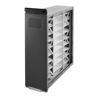
Key instructions for safe and proper installation of the Honeywell Media Air Cleaner.
Details on how the media air cleaner filters air and captures particles.
Discusses compatibility with different HVAC systems and potential issues.
Guidelines for fabricating gradual transitions to optimize airflow and reduce turbulence.
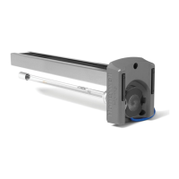
Instructions for installing turning vanes to ensure even airflow across the filter media.
Notes on the adaptability of the media air cleaner to various HVAC systems.
Guidance on attaching an offset fitting for specific furnace duct connections.
Essential safety precautions for personal protection during installation.
Steps to take before physically mounting the air cleaner unit.
Guidance for retrofitting an existing air cleaner with the Honeywell unit.
Mounting the media air filter vertically where return air enters the side inlet of a highboy furnace.
Mounting the media air cleaner horizontally where return air enters from below a highboy furnace.
Mounting vertically on furnace between furnace and louvered return air opening.
Mounting horizontally in return plenum just above furnace and opposite heating plenum.
Mounting horizontally in return duct or plenum just above furnace.
Mounting horizontally in central return duct for central fan installation.
Mounting vertically in return duct near furnace for horizontal furnace.
Using two or more media air cleaners in a high capacity system.
Temporarily place the cabinet to ensure adequate clearance for cartridge removal and replacement.
Align and securely attach the cabinet to the furnace opening using screws, rivets, or slip joints.
Install turning vanes if a 90-degree elbow is directly against the media air cleaner cabinet.
Securely fasten the cabinet to the ductwork using appropriate methods.
Connect vertical duct section to elbow, adjusting for duct length or adding an offset fitting.
Seal all return air system joints between the filter and furnace to prevent dust ingress.
Slide filter cartridge into cabinet, ensuring airflow arrow direction is correct, then close door.
Visually check airflow direction, vane/transition installation, sealed joints, and connections.
Replace access doors and run the furnace/cooling system cycle to verify operation.
Replace filter when pressure drop reaches 0.5 in. w.c. or at least annually.
Notes on factors affecting filter life and recording replacement dates.
Details MERV rating, static pressure drop at 500 FPM for F100 and F200.
Defines efficiency ratings (E1, E2, E3) for small, medium, and large particles.
Graphs showing pressure drop vs. airflow for different filter sizes and models.
Table listing physical dimensions (A, B, C, D) for various filter sizes.
Specifies the acceptable operating temperature range for the unit.
Lists certifications and approvals, such as UL 900 Class 2.
Table correlating filter sizes with Honeywell part numbers for F100 and F200.
| Model Number | FC100A1052 |
|---|---|
| Brand | Honeywell Home |
| Air Filter Type | Pleated |
| MERV Rating | 11 |
| Filter Life | up to 12 months |
| Energy Star Certified | No |