REFLECTOR PANEL HEATER INSTALLATION GUIDE Issue 5 May 2007 2104M0728
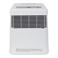
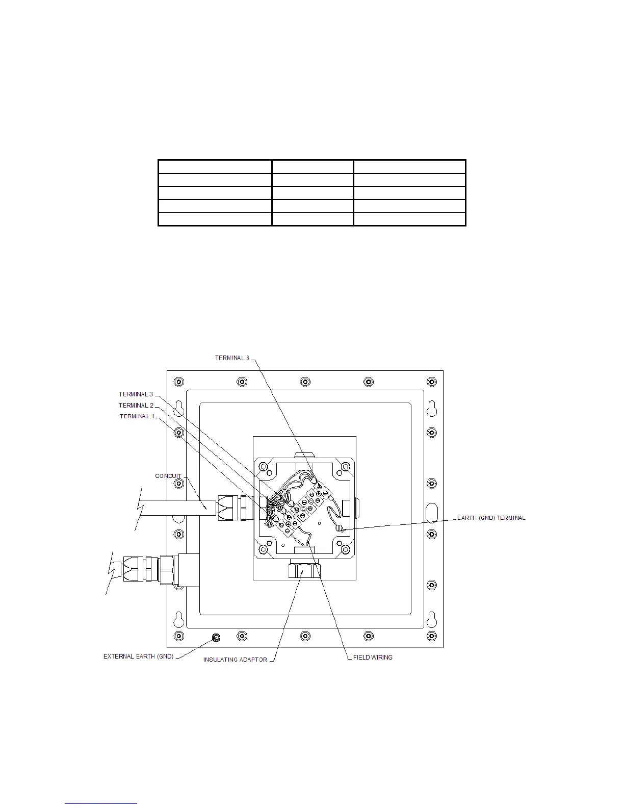
5.2.2 Terminal Connection Diagram- Long Range Reflector Panel Heater
ater is a resistive heater requiring an 18-28Vdc (nominal
4Vdc) supply. All connections are made inside the junction box supplied as part of the
Re
terminals (2 and 3) are available.
The long range Reflector Panel He
2
flector Panel Heater Assembly. To allow for a wide range of supply voltage, two power
Terminal Identification Wire Colour Customer Connection
1 White 0V
2 Black or Brown >20Vdc
3 Blue 18-20Vdc
6 Green Earth
Note: If the voltage drops below 20Vdc in operation, the 24Vdc input should be connected to
terminal 3 instead of terminal 2.
ower supply cable with the Reflector Panel Heater, a
heck must be made to verify that a minimum voltage of 18V is available at the Cross Duct
Excel when th r i
Terminal 2 connects to a 33Ω heater; terminal 3 connects to a 23Ω heater.
If the Cross Duct Excel shares a p
c
e Reflector Panel Heate s operating.
7
 Loading...