INSTALLATION INSTRUCTIONS
393691 LP Gas and 394588
Natural Gas Conversion Kits
FOR VR8200/VR8300/SV9500/SV9600 FAMILY OF
COMBINATION GAS CONTROLS
APPLICATION
The 393691 LP Conversion Kit changes
VR8200/VR8300/SV9500/SV9600 family
combination gas controls from regulated natural gas
to regulated LP gas. The 394588 Natural Gas
Conversion Kit changes
VR8200/VR8300/SV9500/SV9600 family
combination gas controls from regulated LP gas to
regulated natural gas. Kits include a new cap screw,
pressure regulator adjustment screw, spring and
conversion label.
To use this kit, assure gas control is equipped with a
standard or slow opening pressure regulator.
NOTE: Step regulator valves cannot be converted.
INSTALLATION
When Installing this Product…
1. Read these instructions carefully. Failure to
follow instructions can damage product or
cause a hazardous condition.
2. Check ratings given in instructions and on
product to make sure product is suitable for
your application.
3. The installer must be a trained, experienced
service technician.
4. After installation is complete, use these instruc-
tions to check out product operation.
Fire or Explosion Hazard.
Can cause severe injury, death or property
damage.
Follow these warnings exactly:
1. Disconnect power supply before wiring to
prevent electrical shock or equipment
damage.
2. To avoid dangerous accumulation of fuel
gas, turn off gas supply at appliance service
valve before starting installation and
perform Gas Leak Test after completion of
installation.
3. Use only your hand to turn gas control knob.
Never use any tools. If gas control knob will
not operate by hand, then a qualified
technician should replace the gas control.
Force or attempted repair may result in fire
or explosion.
4. Change main and pilot burner orifices to
meet appliance manufacturer
specifications.
To convert from one gas to another:
1. Turn off gas supply at the appliance service
valve.
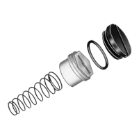
2. Remove regulator cap screw and pressure
regulator adjusting screw. Refer to Fig. 1.
3. Remove the existing spring.
4. Insert the replacement spring. Refer to Fig. 2.
Fig. 1. Top view of VR8200 combination gas control.
OUTLET
PRESSURE
TAP
INLET
OUTLET
WIRING
TERMINALS (2)
INLET
PRESSURE TAP
PRESSURE REGULATOR
ADJUSTMENT
(UNDER CAP SCREW)
CONVENIENCE
TERMINALS (2)
(OPTIONAL)
PILOT OUTLET
PILOT ADJUSTMENT
(UNDER CAP SCREW)
GAS
CONTROL
KNOB
RED
RESET
BUTTON
THERMOCOUPLE
CONNECTION
M8084
1
1
1
THERMOCOUPLE CONNECTION AND RED RESET BUTTON
ON STANDING PILOT MODELS ONLY.