ADEMCO CE3
Code Encryptor 3
INSTALLATION AND SETUP GUIDE
GENERAL INFORMATION
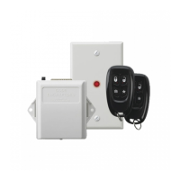
The Code Encryptor 3 (CE3) provides wireless control for
arming/disarming a security system, opening/closing a garage door, and
activating a relay output (ex. turning on a light). The CE3 consists of a
Receiver and wiring harness, remote control keyfob, and a status LED
with optional mounting plate.
The most important factor for range and reliability is the mounting
location of the Receiver. Select a location that is as centrally located as
possible. Keep in mind that the user will want to control the operation of
the garage door from the driveway, and will also expect the use of the
remote for alarm on/off in the area of entry and exit.
Although you can wire the Receiver to the panel, it may reduce labor by
installing the CE3 Receiver at the point of entry and wire it to a nearby
keypad. In most cases this is the garage entry, which will provide an easy
installation for garage door open/close, status indicator, and alarm
controls through the keypad.
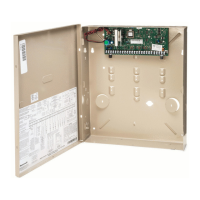
IMPORTANT: Do not mount the Receiver module inside the alarm panel
enclosure; it will reduce the reception of the remote keyfob.
CE3-006-V0
CODE
ENCRYPTOR 3
REMOTE
KEYFOB
LED STATUS INDICATOR
Red = Armed
Green = Disarmed
Yellow = Alarm
LED AND
MOUNTING
PLATE
WIRE
HARNESS
CODE ENCRYPTOR 3
RECEIVER
Installation Steps
1. Connect the CE3 Receiver to the control panel.
2. Program the CE3:
a. Associate the Receiver with the connected control using Automatic Recognition.
b. Program a user code for the Remote Keyfob.
3. Wire optional features, if used (Status LED, Garage Door Opener, Relay Outputs).
4. Test the System.
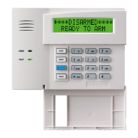
CONNECTING THE RECEIVER TO THE CONTROL PANEL
The Receiver can be wired either to the control’s terminals
or to a keypad’s terminals.
1. Unplug the Receiver from the wire harness.
2. Connect the Red, Black, Yellow and Green wires to the
keypad or control’s terminals as shown in the diagram.
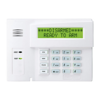
NOTE: You can make these connections at the control or
at the keypad itself. If you place the Code Encryptor 3 in
the garage or any other location away from the control,
you may choose to wire the Code Encryptor 3 directly to
the keypad.
Summary of Basic Connections
Wire Color Connection
Red Keypad Red or Aux (+)
Black Keypad Black or Aux (-)
Green
Keypad Green (control Data In)
†
Yellow Keypad Yellow (control Data Out)
† not used on GE Caddx NX panels
CE3-011-V0
IN OUT
DATAAUX
SYSTEM
KEYPAD
ALARM PANEL
BLACK
RED
GREEN
YELLOW
1
OFF
4
MAX
7
INSTANT
READY
2
AWAY
5
TEST
8
CODE
0
3
STAY
6
BYPASS
#
ARMED
READY
9
CHIME
PROGRAM
BUTTON
LED
CODE
ENCRYPTOR 3
RECEIVER