MERLIN NX ROOM CONTROLLER – INSTALLATION & COMMISSIONING INSTRUCTIONS
23 EN1Z-1035GE51 R0420
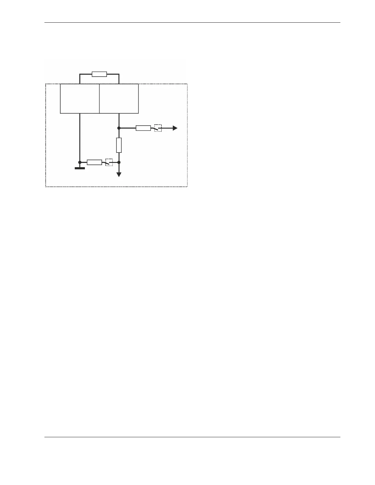
Bias Resistors
Each universal input is equipped with one bias resistor. See
Fig. 29.
UI
GND
SENSOR
R
DOWN
R
BIAS
R
SER
S2
S1
ADC
V
UP
Fig. 29. Schematic of universal inputs and bias resistors
LEGEND:
V
UP
= 10 V (except for UI1-4 of RL8N, which have 24 V).
R
BIAS
= Bias resistor (with a resistance of 24.9 kΩ in the
case of NTC10kΩ andNTC20kΩ sensor inputs,
and 7.5 kΩ in the case of Pt1000 sensor inputs);
can be switched OFF via software by S1 to support
0…10 V inputs without bias current ("high
impedance") – except in the case of UI1-4 of
RL8N, which have a resistance of 11.8 kΩ and
cannot be switched OFF.
R
SER
= Series resistor for voltage dividing and filtering
(with a resistance of 150 kΩ).
R
DOWN
= An internal load resistor (with a resistance of
49 kΩ); depending upon the given type of con-
nected sensor, the firmware may switch this
resistor OFF.
Analog Outputs
The terminal blocks containing the controller's analog outputs
are green. Analog output types: See Table 5.
The analog outputs of the RLxN controllers (large housing)
are protected against voltages of max. 29 VAC and 30 VDC
(due to, e.g., miswiring).
NOTE: Connecting 24 VAC to any analog output of the
RSxN controller (small housing) will damage the
hardware.
 Loading...