EasyManua.ls Logo

Honeywell CLMERL4N User Manual

Honeywell CLMERL4N
34 pages
To Next Page IconTo Next Page
Page #1 background imageLoading...
Page #1 background image
MERLIN NX Room Controller
Installation &
Commissioning
Instructions
® U.S. Registered Trademark
Copyright © 2020 Honeywell Inc. • All Rights Reserved EN1Z-1035GE51 R0420
GENERAL INFORMATION
Fig. 1. CLMERxxN (without optional covers)
BEFORE INSTALLATION
IMPORTANT
It is recommended that the unit be kept at room
temperature for at least 24 hours before applying
power; this is to allow the evaporation of any
condensation resulting from low shipping / storage
temperatures.
US requirement, only: This device must be installed in
a UL-listed enclosure offering adequate space to
maintain the segregation of line voltage field wiring
and Class 2 field wiring.
CAUTION
To avoid electrical shock or equipment damage, you
must switch OFF the power supply before attaching /
removing connections to/from any terminals.
Table 1. Overview of models
OS no.:
CLMER…
power
supply
AOs UIs BIs relays
(A
triacs
(B
total no.
of I/Os
remarks
large housing
(198 x 110 x 57.5
mm)
RL4N 230 VAC 6 10 0 4 4 24 24-hr data retention
RL6N 24 VAC 6 10 0 4 4 24 24-hr data retention
RL8N 230 VAC 6 6
(C
4
(D
4 4 24
24-hr data retention; supports switch
inputs with 24 V pull-up for connection of
standard light switches; preferred model
for light and blinds control
small housing
(162 x 110 x 57.5
mm)
RS4N 230 VAC 4 4 0 4 2 14 24-hr data retention
RS5N 24 VAC 4 4 0 4 2 14 24-hr data retention
(A
See also section "Relay Outputs" on pg. 22.
(B
See also section "Triac Current Limitations" on pg. 22.
(C
Of this model's six UIs, only two UIs support NTC; this model is thus not suitable for the hardwiring of wall modules requiring
three UIs supporting NTC.
(D
This model's four binary-only inputs are labelled as UI1-UI4.
CPU: 32-bit MK24FN Freescale Kinetis Cortex M4
Question and Answer IconNeed help?

Do you have a question about the Honeywell CLMERL4N and is the answer not in the manual?

Honeywell CLMERL4N Specifications

General IconGeneral
BrandHoneywell
ModelCLMERL4N
CategoryController
LanguageEnglish

Summary

General Information and Pre-Installation Guidelines

Pre-Installation Precautions

Important recommendations and safety warnings prior to unit installation.

Dimensions and Mounting Options

Controller Housing Dimensions

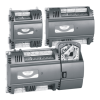
Physical dimensions for the large (RLxN) and small (RSxN) controller housings.

DIN Rail Mounting and Dismounting

Procedures for attaching and removing the controller from a DIN rail.

Terminal Protection Covers for IP30

Covers required for IP30 protection when mounting outside a cabinet.

Wall Mounting and Dismounting

Wall Mounting Drilling Template

A template for drilling screw holes for wall mounting the controller.

Terminal Assignment and Connections

Terminal Assignment Overview

General information on terminal blocks, their functions, and color coding.

Power Supply Terminal Connections

Details on connecting the power supply to the controller's terminals.

Input and Output Terminal Details

Information on analog, binary, and universal input/output terminal configurations.

Communication Interface Connections

Details on connecting communication interfaces like Sylk Bus and RS485.

Power Supply and Wiring Information

General Power Supply Information

General guidelines and precautions for power supply connections.

Wiring Specifics for Power Supply

Details on wiring for 230-VAC and 24-VAC models and terminal specifications.

Communication and Signal Terminal Wiring

Wiring specifications for communication and signal terminals.

Electrical Data and Specifications

Electrical Data for All Models

Electrical specifications applicable to all 230 VAC and 24 VAC models.

Freely Programmable Applications Overview

Supported Actuators and Sensors

Lists supported actuators and sensors for programmable applications.

Application Control and Blinds Functionality

Details on applications, blinds control, manual positioning, and commands.

Emergency Commands and Feedback

Information on emergency commands and feedback from function blocks.

Light and Blinds Control Features

Commissioning Parameters and Hardware

Parameters for commissioning blinds and lights, and hardware recommendations.

Light Function Block and Operation

Details on the light function block and manual ON/OFF/Dim control.

Light Control Application Details

Light Control Inputs and Commands

Information on application commands, manual inputs, sensors, and emergency commands.

Light Control Wiring and Recommendations

Wiring examples and recommendations for light control.

Commissioning Procedures

Automatic MAC Addressing

How the controller automatically assigns MAC addresses on a BACnet MS/TP channel.

Operator Interfaces and Controls

Controller LEDs and Status Indicators

Description and behavior of the controller's status and power LEDs.

Service Button Operation

How to use the service button during power-up and normal operation.

Communication Interfaces and Standards

Overview of Communication Interfaces

General overview of communication interfaces and system diagram.

TIA/EIA-485 Standard Compliance

Requirements and specifications for TIA/EIA-485 standard cabling.

BACnet MS/TP Interface and Considerations

Details on the BACnet MS/TP interface, baud rates, and cable length.

Network Connection Details

BACnet MS/TP Bus Connectivity

Notes on connecting to a BACnet MS/TP bus and limitations.

BACnet WiFi Adapter Connection

Information on connecting the BACnet WiFi Adapter via RJ45.

Modbus Interface Configuration

Modbus Wiring, Cables, and Specifications

Details on Modbus wiring topology, cables, shielding, and master specifications.

Modbus Interface Considerations

Important considerations for using the Modbus interface.

Sylk Bus Connectivity

Sylk Bus Interface Description

Information on the Sylk interface, its capabilities, and current limits.

Input/Output Terminal Details

Power Output Terminal Current Limits

Maximum current output limitations for power terminals on 230 VAC and 24 VAC controllers.

Relay and Triac Output Types

Description of relay and triac outputs, including current limitations.

Universal Input Functionality

Information on universal input types and their protection.

Bias Resistors in Sensor Inputs

Schematic of Bias Resistors

Diagram showing the schematic of universal inputs and bias resistors.

Analog Output Specifications

Analog Output Protection and Notes

Protection details for analog outputs and important notes.

Wall Module Integration and Configuration

Wall Module Functions and Configuration

Overview of supported wall module functions and configuration options.

Wall Module Display Information Configuration

How to configure wall module LEDs and LCDs for displaying status information.

Wall Module Display Screen Examples

Unoccupied and Standby Mode Screens

Examples of screen displays for unoccupied and standby modes.

Occupied Mode Display Screens

Examples of screen displays for the occupied mode.

TR42x Wall Module Configuration

Fan and HVAC Configuration Options

How to configure fan operation and heating/cooling modes on the TR42x.

Expanded Menu Operation

How to access and navigate the expanded menu for settings.

Troubleshooting and System Classification

System Classifications and Environmental Limits

Classification of the device and environmental operating limits.

Related Technical Literature

Technical Literature References

List of related documents for further information.

Sensor Characteristics and Accuracy

Sensor Input Accuracy Specifications

Typical accuracies for NTC10kΩ and NTC20kΩ sensor inputs.

Sensor Failure Recognition Thresholds

Thresholds for recognizing sensor breaks and short-circuits.

Trademark Information

Trademarks and Manufacturing Credits

Information on trademarks and manufacturing details.

Related product manuals