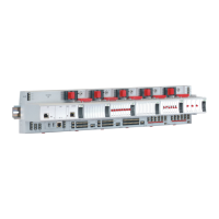
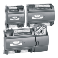
MERLIN NX ROOM CONTROLLER – INSTALLATION & COMMISSIONING INSTRUCTIONS
EN1Z-1035GE51 R0420 4
Table 2. RSxN Room Controller: Overview of terminals and functions
term. printing function RS4N RS5N
1, 2 "L", "N" 230-V power supply X --
3, 4 "24V~", "24V0"
Removable 24-V power supply input and aux. output voltage (24 VAC)
for all triacs
X --
3, 4 "24V~", "24V0" Aux. output voltage (24 VAC) for all triacs -- X
5 "TN" Aux. term. for triac neutral wiring (internally connected with terminal 8) X X
6 "T~" Triac input voltage (24 VAC / 230 VAC) for all triacs; triac-switched X X
7 "T01" Triac-switched output X X
8 "TN" Aux. term. for triac neutral wiring (internally connected with terminal 5) X X
9 "T02" Triac-switched output X X
10, 11 "RO4", "IN4" Output of Relay 4, Input for Relay 4 type 2 type 2
12, 13 "RN", "RN" Aux. terminals for relay neutral wiring X X
14, 15 "IN1", "RO1" Input for Relay 1, Output of Relay 1 type 1 type 1
16, 17 "IN2", "RO2" Input for Relay 2, Output of Relay 2 type 1 type 1
18, 19 "IN3", "RO3" Input for Relay 3, Output of Relay 3 type 1 type 1
20, 21 "WM1", "WM2" Removable interface for Sylk Bus X X
22, 25 "24V~", "24V0"
Removable aux. power (24 VAC 20%, 50/60 Hz)
X X
23, 24, 25 "C2+", "C2-", "24V0" Removable RS485 Modbus interface + corresponding GND X X
26 "AO1" Analog Output 1 type 2 type 2
27 "24V~" 24 VAC power for field devices X X
28 "GND" Ground for AOs X X
29 "AO2" Analog Output 2 type 1 type 1
30 "AO3" Analog Output 3 type 1 type 1
31 "24V~" 24 VAC power for field devices X X
32 "GND" Ground for AOs X X
33 "AO4" Analog Output 4 type 1 type 1
34 "UI1" Universal Input 1 type 1 type 1
35 "GND" Ground for UIs X X
36 "UI2" Universal Input 2 type 1 type 1
37 "UI3" Universal Input 3 type 1 type 1
38 "GND" Ground for UIs X X
39 "UI4" Universal Input 4 type 1 type 1
40, 41, 42 "C1+", "C1-", "GND" Removable BACnet MS/TP interface and corresponding GND X X
Relay output types: See Table 3. Universal input types: See Table 4. Analog output types: See Table 5.
Table 3. Relay output types and characteristics
type 1 (standard) type 2 (high in-rush current)
corresponding ROs of RSxN RO1, RO2, RO3 RO4
corresponding ROs of RLxN RO2, RO3 RO1, RO4
contact N.-O. N.-O.
min. load 5 VAC, 100 mA 24 VAC, 40 mA
switching voltage range 15 … 253 VAC 15 … 253 VAC
max. continuous load at 250 VAC (cos φ = 1) 4 A 10 A
max. continuous load at 250 VAC (cos φ = 0.6) 4 A 10 A
in-rush current (20 ms) -- 80 A
usage fan motor light switching and fan motor
NOTE: The max. sum load of all relay currents at the same time is 14 A.

 Loading...


