MERLIN NX ROOM CONTROLLER – INSTALLATION & COMMISSIONING INSTRUCTIONS
21 EN1Z-1035GE51 R0420
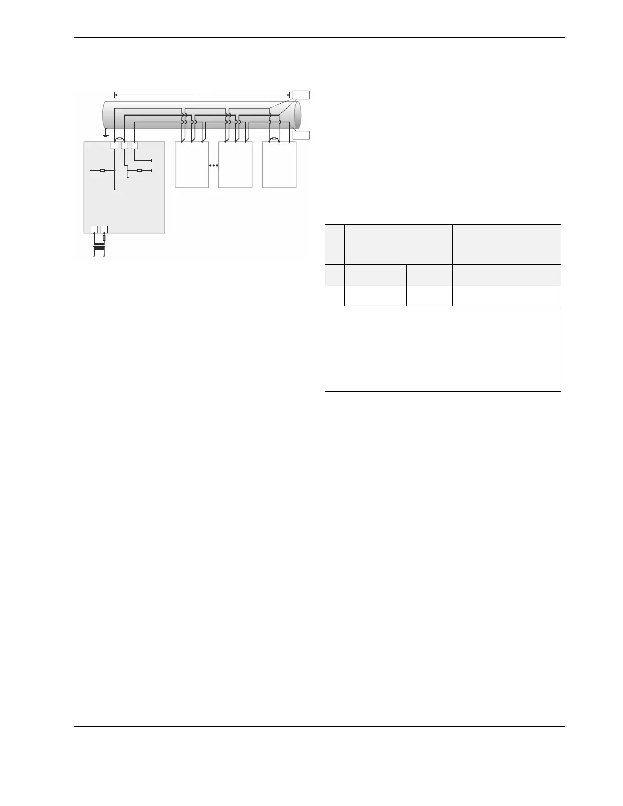
Example: RSxN Modbus Master Controller and Connected
Modbus Slaves (with inserted termination resistors)
24V~
24~0
F1
230 V
24 V
L
RSxN
Modbus Device #1
(MASTER)
GND
GND
+5V
ISO
RS485 (+)
RS485 (-)
550 OHM 550 OHM
RS485 +
RS485 -
GND
RS485 +
RS485 -
GND
RS485 +
RS485 -
GND
Modbus
DEVICE #2
(SLAVE)
Modbus
DEVICE #N-1
(SLAVE)
Modbus
DEVICE #N
(SLAVE)
23
24
25
2
120Ω120Ω
1
TWISTED
PAI R
NOTE 1
GENERIC GENERIC GENERIC
Fig. 28. Connection of an RSxN Modbus master via its
RS485 interface to a Modbus with slaves
With regards to Fig. 28, please note the following:
NOTE 1: If any of the devices are electrically isolated, it is
recommended that those devices be connected to
the ground terminal (GND), if available. See section
"The TIA/EIA-485 Standard" on pg. 18.
NOTE 2: 120-Ohm termination resistors must be inserted
directly into the terminals of both end devices.
NOTE 3: If shielding is used, the shielding of each individual
bus segment should be separately connected at one
end to earth.
NOTE 4: Always power each controller and the connected
slaves via separate transformers.
NOTE 5: Between devices equipped with non-isolated RS485
bus interfaces, potential differences of max. ±7 V are
allowed. Further, this bus should not extend beyond
a single building.
Sylk Bus
The controller features a removable Sylk interface for con-
nection to Sylk Bus-capable devices (e.g., the
CLCMTR40x/42x):
▪ RLxN: terminals 30 and 31;
▪ RSxN: terminals 20 and 21.
The terminal block containing it is gray.
▪ A max. of three CLCMTR40x/42x wall modules can be
supported by a single controller.
▪ The Sylk Bus is single pair, and polarity-insensitive.
▪ Max. current provided at the Sylk Bus interface: 96 mA.
Table 11. Recommended max. distances from controller
to CLCMTR40x/T42x wall modules
no.
single twisted pair, non-
shielded, stranded or solid
A)
standard non-twisted
thermostat wire, shielded or
non-shielded, stranded or
solid
B), C)
0.33…0.82 mm
2
(18…22 AWG)
0.20 mm
2
(24 AWG)
0.20…0.82 mm
2
(18…24 AWG)
2
150 m
(500 ft)
120 m
(400 ft)
30 m (100 ft)
A)
As a rule of thumb, single twisted pair (two wires per cable, only),
thicker gauge, non-shielded cable yields the best results for longer
runs.
B)
The 30 m (100 ft) distance for standard thermostat wire is con-
servative, but is meant to reduce the impact of any sources of
electrical noise (incl. but not limited to VFDs, electronic ballasts,
etc.). Shielded cable recommended only if there is a need to reduce
the effect of electrical noise.
C)
These distances apply also for shielded twisted pair.
 Loading...