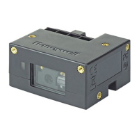
The CM Series 2D Imager Module is a range of compact, encased 2D imager modules designed for fixed mount applications. These modules are manufactured by Honeywell, a company that emphasizes "THE POWER OF CONNECTED." The series includes models such as the CM5680, CM3680, and CM2180. This Quick Start Guide provides essential information for setting up and using these devices.
Function Description
The primary function of the CM Series 2D Imager Module is to scan and decode 2D barcodes. It operates as a data capture device, converting visual barcode information into digital data that can be processed by a host system. By default, the scanner utilizes a USB serial interface for communication with a host. This allows for straightforward integration into various systems that support USB connectivity. The module is designed to be a reliable component in fixed mount applications, where it can be integrated into larger systems or kiosks for automated or semi-automated scanning tasks.
Usage Features
The CM Series 2D Imager Module comes equipped with several features that facilitate its use and integration:
- USB Interface (micro USB connector): This is the primary method for connecting the module to a host system. The use of a micro USB connector ensures compatibility with standard USB cables.
- Exit Window: This is the transparent area through which the imager captures barcode data. It is crucial for the module's scanning functionality.
- Beeper: The module includes an audible beeper that provides feedback to the user, typically indicating successful scans or error conditions. The beeper's volume can be configured to suit different operating environments.
- Status Indicator: A visual status indicator is present on the module, offering immediate feedback on its operational state. This can help users quickly ascertain if the device is powered on, scanning, or encountering an issue.
- Mounting Holes: The module features multiple mounting holes (x10) to support various mounting positions. This flexibility allows for secure and stable installation in diverse fixed mount applications.
- Sealed Enclosure: The module is housed in a sealed enclosure, which helps protect its internal components from environmental factors, contributing to its durability and reliability in industrial or demanding settings.
- Cable Management: A slider mechanism is provided to secure the USB cable to the module, ensuring a tight and stable connection. This prevents accidental disconnections and provides strain relief for the cable.
Connecting to a Host:
Connecting the CM Series module to a host involves a few simple steps:
- Remove the slider: The cable slider needs to be removed by pressing its ends and sliding it off the module.
- Connect the USB cable: A standard USB-A to micro USB cable is connected to the module's micro USB port. The maximum recommended length for this cable is 3-5 meters.
- Secure the cable: The cable is then routed through the center of the slider, and the slider is pressed back onto the module until it is tight, securing the cable.
- Connect to host: Finally, the USB cable is connected to the host system.
- Power-up: Upon powering up the host, the scanner will power up, emit a series of beeps from low to high, and its lighting will turn on. The device supports "hot plugging," meaning the host does not need to be powered down before connecting the module.
Configuration:
The CM Series 2D Imager Module can be configured in two primary ways:
- Reading Configuration Barcodes: Users can scan specific configuration barcodes to set up the scanner. A comprehensive list of available configuration barcodes can be found in the CM Series 2D Imager Module User Guide.
- Using the EZConfig Cloud for Scanning Tool: This online tool provides a more interactive way to configure the scanner. Users can access it via the Honeywell website, navigate to the Device Management section under Browse Products, and then select EZConfig Cloud for Scanning. Registration is required for free access.
Basic Setup Options:
Several basic configuration options are available through barcodes for quick setup:
- Interface Selection: The module can be set to either USB Serial Interface (default) or USB PC Keyboard mode. For USB serial interface, a specific USB driver must be installed, which can be found on hsmftp.honeywell.com.
- Keyboard Country Layout: The default keyboard layout is United States, but options for French, German, and Italian are also available.
- Beeper Volume: The beeper volume can be adjusted to Low, Medium, High (default), or turned Off.
- All Symbologies: Users can enable or disable all symbologies for scanning.
- Presentation Mode: This mode optimizes scan speed with a limited reading range. The scanner LEDs remain dim and the aimer is off until movement is detected, at which point the aimer turns on and LEDs light up to read the barcode. An "Extended Reading Range" option is also available, which optimizes reading range at a lower scan speed.
- Streaming Presentation: In this mode, the scanner LEDs are continuously on, and the aimer is off until movement is detected. It offers "Normal" (fast scan speed, limited reading range) and "Enhanced" (fastest possible scan speed, slightly less reading range) options.
- Reset Factory Defaults: A dedicated barcode allows users to reset the module to its original factory settings.
Maintenance Features
While the guide does not explicitly detail maintenance features, it provides recommendations that contribute to the longevity and optimal performance of the device:
- No Additional Exit Window: It is recommended not to add an exit window over the existing exit window. This suggests that the integrated exit window is designed for optimal performance and adding another layer could interfere with scanning accuracy or light transmission.
- Unobstructed Beeper Opening: For the best beeper performance, it is advised not to fully cover the beeper opening. This ensures that the audible feedback remains clear and effective.
- Secure Cable Connection: The recommendation to ensure the cable is fitted tightly in the connector using the cable slider, and that the cable overmold does not exceed 23 mm/0.90 in., is crucial for maintaining a reliable power and data connection. A loose connection can lead to intermittent operation or damage over time.
The sealed enclosure, as mentioned in the usage features, also inherently contributes to maintenance by protecting the internal electronics from dust, moisture, and other contaminants, thereby reducing the need for frequent cleaning or repair of sensitive components. The availability of additional documentation, such as the CM Series 2D Imager Module User Guide, further supports maintenance by providing detailed information for troubleshooting and advanced configurations. Honeywell also offers support through a knowledge base and technical support portal, and provides warranty information, indicating a commitment to product support and potential repair services.