Fire Alarm Control Panel IQ8Control C / M
FB 798951.10.GB0 / 04.15 55
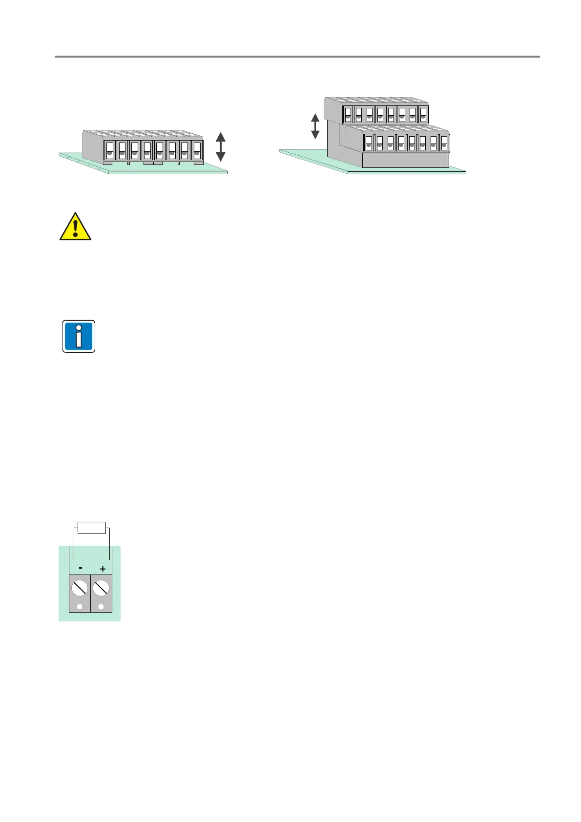
Connection terminals
removable
removable
X4
IN - top
OUT - bottom
Fig. 45: Connection terminals Connection terminals fire department operating panel
Observe permitted torque (max. 0.4 Nm) of the terminals!
Connection of the micro module
Eight connecting terminals are provided for the micro module slot of the Field device module. The actual
connection of the eight terminals depends on the type of module used.
If an essernet
®
micro module is used, this module may only be inserted into the micro module slot
of the basis module. The essernet
®
micro module requires adaptation of the terminal card on the
basis module. The EMI protection must be implemented by external EMI-protection devices.
Primary loop input Pri+/Pri-
Monitored primary loop input Pri+/Pri- (terminal X8) has the purpose of monitoring CPU failure in the essernet
®
.
These terminals are used, for example, to connect the common fire relay of another Fire Alarm Control Panel. In
the event of trouble in the essernet
®
micro module, a fire alarm signal may still be sent via the relay contact to the
primary loop input of this control panel. The display at this Fire Alarm Control Panel will then show the message
>Prim. loop fire< in the event of an incident occurring.
The primary loop input can be switched off or on and reset via the corresponding primary loop number.
GR1
10K
R*
R* = monitored end-of-line resistor 10 k
R= 10 k
Normal status
R= 5 k
Fire alarm, display >Prim. loop fire<
R= 1 k
Trouble
Primary loop no.: xx24 (xx = Panel no. 01-31)
Fig. 46: Primary loop input Pri+/Pri-
 Loading...


