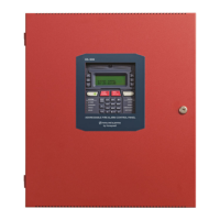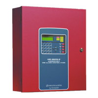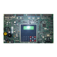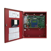
Do you have a question about the Honeywell Fire-Lite Alarms ES-200X and is the answer not in the manual?
| Type | Fire Alarm Control Panel |
|---|---|
| Output Voltage | 24VDC |
| Operating Temperature | 32°F to 120°F (0°C to 49°C) |
| Compatibility | Compatible with Fire-Lite devices |
| NAC Circuits | 4 |
| Power Supply | 120 VAC, 60 Hz |
| Battery Charging Current | 1.0 A |
| Dimensions | 14.5" x 12" x 3.5" |
| Relative Humidity | 93% RH noncondensing |
| Power | 120 VAC, 60 Hz |
Lists key features and optional capabilities of the ES-200X panel, covering its functionalities and compatibility.
Explains the function and addressing of intelligent, addressable smoke and heat detectors.
Describes the function and addressing of intelligent, addressable control and monitor modules.
Lists accessories for addressable devices, including EOLRs and power supervision relays.
Details the FS-Tools utility for local or remote programming, upload, and download of FACP data.
Describes the optional dress panel DP-ES-R, required by ULC for Canadian installations.
Describes the optional trim ring (TR-CE) for semi-flush mounting the FACP backbox.
Details the BB-26 and BB-55F battery boxes for housing batteries and chargers.
Provides information on CHG-75 and CHG-120F battery chargers for lead-acid batteries.
Information on calculating ANN-BUS wire distances and wiring configurations.
Methodology for determining the correct wire gauge and maximum wiring distance for ANN-BUS modules.
Details on REN, AC Impedance, FCC Part 68 compliance, and RJ31X jack installation.
Explains telephone company rights and potential impacts on panel operation, including service discontinuance.
Provides specific notices and cautions for Canadian installations, including Industry Canada compliance.
Provides detailed instructions for mounting the FACP backbox, including static precautions.
Covers the essential steps for connecting AC power, earth ground, and battery power to the FACP.
Describes the function and wiring of the FACP's programmable and fixed trouble relays.
Details the four NACs, their capabilities, and requirements for connecting notification appliances.
Explains how to synchronize notification appliances using the remote sync output.
Details the critical requirements for separating and routing power-limited and nonpower-limited wiring.
Covers the installation, wiring, and dip switch configuration for the IPOTS-COM communicator.
Outlines installation procedures for optional modules like GSM communicators, NAC expanders, and transmitter modules.
Describes how the FACP controls audio systems like ECC-50/100 and ANN-BUS connections.
Explains how to input programming data using the FACP keypad or a computer keyboard.
Outlines the different methods available for programming the ES-200X system.
Details the two user programming levels and the use of factory-set and user-defined passwords.
Describes how to access and navigate the Master Programming Level, including autoprogramming.
Explains how to add, delete, or edit addressable detectors and modules in the system.
Covers procedures for enabling, disabling, and configuring special purpose zones.
Details how to configure the SLC loop class (A/B) and select the loop protocol (CLIP or LiteSpeed).
Outlines configuration options for panel features like function keys, banner, time-date, NACs, and relays.
Describes how to view and erase system event history.
Details configuration settings for the pre-installed IPOTS-COM and optional CELL-MOD/CELL-CAB-FL communicators.
Explains how to configure primary and secondary communication paths for central station reporting.
Covers configuration of ANN-BUS annunciators, including setup, enabling, and module addressing.
Describes how to change the Master, Maintenance, and Remote Download passwords.
Explains how to clear system programming or specific points/devices.
Details how to check for NACs or zones programmed without input or output assignments.
Provides access to maintenance functions like disabling points, viewing history, and checking programs.
Outlines how to perform a system walktest, including silent, audible, and viewing logs/points.
Covers system configurations like NAC enablement, remote sync, time/date, charger, and 4XTMF supervision.
Details how to enable, disable, and configure special purpose zones.
Explains the function of panel control buttons like Acknowledge, Alarm Silence, Drill, Reset, and Function Keys.
Describes the meaning and operation of the 11 LED indicators on the front panel.
Describes the system's behavior and functions when no alarms or troubles are present.
Explains how the system indicates and handles trouble conditions, including display messages and relay activation.
Details how the system operates during an alarm condition, including LED indicators and display messages.
Describes the specific behavior and display messages for a Carbon Monoxide (CO) alarm.
Explains the system's operation and display during supervisory conditions.
Outlines the system's behavior for process monitor events, including piezo, LCD, and relay activations.
Describes the system's response to manual hazard or tornado condition activations.
Details the system's behavior for manual medical alert activations.
Explains FACP integration with audio systems for mass notification and override capabilities.
Covers the programmable options for the four Notification Appliance Circuits.
Explains how addressable devices are assigned to software alarm zones.
Describes how input and output points can be disabled or enabled.
Details the behavior of waterflow circuits regarding alarm silence.
Covers detector monitoring for maintenance, automatic testing, type code supervision, and alarm verification.
Explains the FACP's built-in clock for time, date, and daylight savings.
Details how to synchronize notification appliance activations.
Lists available pulse rates for programmed coded operation on NAC circuits.
Explains the configuration of presignal operation for initiating devices.
Details the configuration of the Positive Alarm Sequence (PAS) for smoke detectors.
Covers various special system timers including silence inhibit, autosilence, and trouble reminder.
Outlines how to perform a system walktest for testing alarm devices and storing results.
Describes how to view system status and programmed features without requiring a password.
Lists the priority order for transmitting events to central stations.
Details using the FS-Tools utility for programming, uploading, and downloading FACP data.
Explains the process of transferring system programs via FS-Tools or USB.
Explains how to transfer programming information to and from the FACP using a USB flash drive.
Provides instructions for upgrading the embedded software (firmware) of the FACP.
Introduction to calculating power supply currents in alarm and standby conditions.
Guides the user in calculating the required AC branch circuit current for the system.
Details the calculation of system current loads for both primary (AC) and secondary (battery) power.
Details the process for calculating required battery size based on standby and alarm loads, including NFPA requirements.
Explains how addressable devices are mapped to software zones and provides examples.
Illustrates the connection of the MBT-1 for municipal box trip, enabling silencing functionality.
Lists NAC wiring requirements, including maximum allowable wire lengths and gauges.
Details how to program control modules for HVAC shutdown during fire alarms.
Explains how monitor modules can be used for HVAC restart or override functions.
Describes the transmission string format for Ademco Contact ID reporting.
Provides an example of alarm and trouble reports in the Ademco Contact ID reporting structure.
Provides immediate actions for audible alarms, including evacuation and notification procedures.
Outlines steps for notifying monitoring services and first responders for non-alarm events.
Instructions for safely clearing the area and resetting the control panel after an alarm.
Describes system behavior during power loss and the need for authorized service.
Explains how to manually activate NACs using the DRILL button and notes for 4XTMF module.
Details how to silence audible notification appliance circuits and the conditions for reactivation.
Procedure for testing all panel indicators, LCD display, and piezo sounder.


