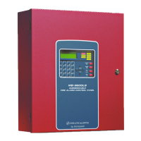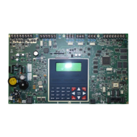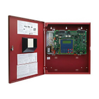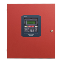
Do you have a question about the Honeywell Fire-Lite Alarms MS-9200 and is the answer not in the manual?
| Type | Addressable Fire Alarm Control Panel |
|---|---|
| NAC Circuits | 4 |
| SLC Loops | 1 |
| Operating Voltage | 24VDC |
| Operating Temperature Range | 32°F to 120°F (0°C to 49°C) |
| Humidity Range | 10% to 93% non-condensing |
| Power Supply | 120VAC, 60Hz |
| Battery Backup | 24 VDC, 7 Ah minimum |
| Communication | Optional Dialer or Ethernet |
| Dimensions | 14.5" H x 3.5" D |
Warning on power disconnection for servicing and caution for re-acceptance testing after changes.
Precautions for temperature, wire size, lightning, static, and display cleaning.
FCC warning regarding radio frequency energy and Canadian requirements for digital apparatus.
Recommendation to download latest software versions for optimal product functionality and features.
Guidance on providing feedback for improving documentation accuracy and content.
Describes operation, installation, and wiring of SLC devices with Fire-Lite control panels.
Details legacy vs. newer module and detector base styles, noting differences in rotary dials and terminals.
Lists essential documents for additional information on control panels and SLC devices.
Explains SLC communication, surge suppression, and LiteSpeed/CLIP polling protocols.
Specifies wire gauge/type for CLIP/LiteSpeed modes based on distance.
Procedures for measuring DC resistance and total wire length for SLC circuits.
Methods for measuring DC resistance and total wire length in two-wire and four-wire SLCs.
Details correct method for terminating shield drain wire and foil, with cautionary notes.
Describes power and SLC terminal blocks for MS-9200 and MS-9600 series panels.
Details terminal blocks for MS-9200UDLS (Rev 3), MS-9200UD/UDLS (Rev 1&2), and MS-9050UD.
Describes power and SLC terminal blocks for ES-50X and ES-200X control panels.
Introduces NFPA Class B and Class A SLC circuits not requiring isolation devices.
Illustrates typical wiring for a supervised Class B SLC, allowing T-tapping.
Illustrates typical wiring for a Class A SLC, prohibiting T-tapping.
Introduces isolator modules (1300, ISO-6) and bases for circuit fault protection.
Provides typical wiring diagrams for 1300 and ISO-6 isolator modules.
Illustrates Class B SLC operation with 1300 and ISO-6 isolator modules for branch protection.
Details Class A SLC protection using flanking 1300 isolator modules to protect sections.
Explains Class X operation with isolator modules flanking each device for fault protection.
Covers addressable monitor modules for IDCs and details the MMF-300.
Interfaces with FACP for up to ten Class B or five Class A IDCs.
Monitors a single IDC of UL-listed two-wire 24V conventional smoke detectors.
Interfaces with up to six Class B or three Class A IDCs for conventional alarm systems.
Provides two independent 2-wire IDCs at consecutive addresses.
Functionally identical to MMF-300, in a smaller package for direct mounting.
Important note about not mixing services on the IDC for these modules.
Procedures for setting SLC addresses on single and multi-point modules.
Typical wiring for a supervised Class B IDC using an MMF-300 module.
Typical wiring for a supervised Class A IDC using an MMF-300 module.
Wiring for supervised, power-limited emergency signaling circuits using an MMF-300 module.
Typical wiring for a supervised Class B IDC using an MMF-300-10 module.
Typical wiring for a supervised Class A IDC using an MMF-300-10 module.
Typical wiring for a supervised Class B IDC using an MDF-300 dual monitor module.
Typical wiring for a supervised Class B IDC using an MMF-302 module.
Typical wiring for a supervised Class A IDC using an MMF-302 module.
Typical wiring for a supervised Class B IDC using an MMF-302-6 module.
Typical wiring for a supervised Class A IDC using an MMF-302-6 module.
Describes CMF-300/CMF-300-6 modules for NAC power and lists relay contact ratings.
Details CMF-300 installation, address setting, and NAC wiring.
Typical wiring for supervised Class B and Class A NACs using a CMF-300 module.
Covers cabinet installation, SLC addressing, NAC class selection, and address disabling.
Details short circuit protection and notes unsupported features for CMF-300-6.
Diagram and explanation of CMF-300-6 circuit board components and settings.
Typical wiring for a supervised Class B NAC using a CMF-300-6 module.
Typical wiring for a supervised Class A NAC using a CMF-300-6 module.
Describes CRF-300/CRF-300-6 modules providing Form-C relay contacts and their ratings.
Details CRF-300 installation, address setting, and Form-C relay wiring.
Diagram and explanation of CRF-300-6 circuit board components and settings.
Covers CRF-300-6 cabinet installation, SLC addressing, and Form-C relay wiring.
Functions as two relay control modules and two Class B monitor modules; lists ratings.
Details CDRM-300 installation, address setting, and wiring for Form-C relay.
Describes detector bases (plug-in, sounder, relay, isolator) and W-GATE wireless gateway.
Procedure for setting SLC address using rotary switches on intelligent detectors.
Typical wiring diagram for B300-6, B210LP, or B501 detector bases.
Illustrates wiring for B224BI isolator base and B224RB relay base.
Typical wiring for B200S sounder bases and W-GATE wireless gateway.
Details W-GATE terminal layout and powering from SLC loop or external source.
Shows wiring for powering the W-GATE using an external regulated 24VDC power source.
Describes beam detectors for open areas and covers setting SLC address.
Illustrates typical wiring connections for the OSI-RI-FL beam detector.
Describes BG-12LX pull station and covers setting SLC address.
Shows typical wiring connections for the BG-12LX manual pull station to an SLC.
Provides equations to determine minimum resistance for 24 VDC power runs to devices.
Lists minimum supply voltages for Fire Lite power supplies used with FACPs.
Explains using power supervision relays to monitor 24 VDC power for detectors and NACs.
Lists approved surge protectors and general requirements for SLC wiring outside buildings.
Details mounting, connection, and grounding requirements for surge suppressors.
Wiring diagrams for surge protectors with MS-9200 panels.
Wiring diagrams for surge protectors with MS-9600 series and MS-9050UD panels.
Wiring diagrams for surge protectors with ES-50X and ES-200X panels.
Compares legacy (V-Type) and newer (H-Type) terminal numbers for the CRF-300 module.
Compares legacy and newer terminal numbers for CMF-300 and MMF-302 modules.
Compares legacy and newer terminal numbers for the MMF-300 module.
Compares legacy and newer terminal numbers for the MDF-300 module.
Shows wiring for legacy B350LP or B501 detector bases, including optional annunciator.
Illustrates wiring for B224BI isolator base and B224RB relay base.
Illustrates wiring for legacy B501BH(-2) and B501BHT(-2) sounder bases.
Lists UL and ULC listed SLC devices including detectors, bases, modules, and controls.
Provides descriptions for Canadian versions of isolator, multi-input/output, control, and relay modules.
Outlines warranty period, exclusions, and conditions for Fire-Lite products.
Describes the procedure for submitting and processing warranty claims.


