Do you have a question about the Honeywell FIRE-LITE MS-10UD Series and is the answer not in the manual?
| Type | Addressable Fire Alarm Control Panel |
|---|---|
| Number of Zones | 10 |
| NAC Circuits | 2 |
| Signaling Line Circuits (SLCs) | 1 |
| Operating Voltage | 24 VDC |
| Operating Temperature Range | 32°F to 120°F (0°C to 49°C) |
| Dimensions | 3.5" |
| Power Supply Current | 3.0 A |
| Battery Charging Current | 1A |
| Auxiliary Power Output | 24 VDC |
| Model | MS-10UD |
Lists key features of the panels, including DACT, IDCs, NACs, relays, and modules.
Details technical specifications for AC Power, Battery, and Initiating Device Circuits.
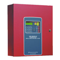
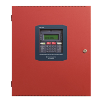
Describes the LCD display, key panel functions, and LED indicators for system status.
Explains DACT functions for communicating system status to a central station.
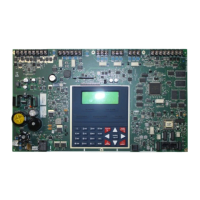
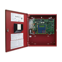
Details the main circuit board, power supply, cabinet, and optional modules.
Lists and describes optional modules like CAC-5X, 4XTMF, and annunciators.
Outlines requirements and warnings for connecting to telephone lines, including FCC compliance.
Provides instructions and safety precautions for mounting the backbox securely.
Details primary AC power connections, earth ground, and secondary battery power source.
Explains the IDCs, their compatibility, and supervision requirements for initiating devices.
Covers total current draw for NACs and DC outputs, supervision, and special application power.
Outlines rules for separating power-limited and nonpower-limited wiring within the cabinet.
Details the connection of telephone lines and the DACT's critical placement for proper function.
Guides the installation of optional modules like CAC-5X, 4XTMF, and ANN-SEC.
Provides guidelines for connecting ANN-BUS devices, including wiring and addressing.
Describes methods for site-specific programming using the FACP keypad or PC.
Details how to enter and navigate the Master Programming Level for system configuration.
Explains maintenance level access for enabling/disabling zones, history, and walktest.
Explains the functions of panel buttons (Acknowledge, Silence, Drill, Reset) and LED indicators.
Details how the FACP indicates and reports system troubles, including LCD messages.
Explains alarm operation, including piezo sounder, Fire Alarm LED, and LCD display messages.
Describes supervisory operation, its differences from alarm, and how conditions are displayed.
Describes the walktest feature for one-person testing of the fire alarm system.
Explains how to enter and use Read Status mode to view programmed features and panel status.
Lists the priority order for events transmitted to the central station, from alarms to 24-hour tests.
Details how to enable remote download, set proprietary mode, and accept downloads.
Guides calculating current draws for non-fire, fire alarm, and standby conditions using provided tables.
Details how to calculate the total standby and alarm load in ampere hours (AH) for battery sizing.
Describes the transmission string format for Ademco Contact ID to the central station receiver.
Lists the minimum system components required for control panel compliance with NFPA standards.
Details additional equipment needed for NFPA 72 Central Station, Auxiliary, and Proprietary Fire Alarm Systems.
Lists NAC wiring requirements for MS-5UD-3(E) and MS-10UD-3(E) using the FLPS-3 power supply.
Provides a list of programming options and their factory default settings for the FACP.
Details ANN-LED annunciator installation for Canadian applications, including programming and wiring.


