24 MS-5UD & MS-10UD Series Manual — P/N 52626:C7 6/12/2018
Installation Input Circuits
2.3 Input Circuits
The MS-5UD has five IDCs (Initiating Device Circuits) and the MS-10UD has ten IDCs. Each circuit is compatible with System Sen-
sor’s i
3
smoke detectors which generate a maintenance signal when the detector becomes dirty and a separate supervisory ‘freeze’ signal
when ambient temperature falls below the detector rating of approximately 45
o
F. The maximum loop resistance limit for each IDC is 100
ohms (700 ohms per zone for linear heat detection). Do not use 2-wire smoke detectors on input zones used for linear heat detection. The
field wiring for each zone is supervised for opens, shorts and ground faults. All conditions are visually and audibly annunciated.
Each circuit is configured for Style B (Class B) operation and will accept i
3
smoke detectors, any normally-open contact devices as well
as conventional 2-wire or 4-wire, 24 VDC smoke detectors. Refer to the Fire•Lite Device Compatibility Document for a list of compati-
ble devices.
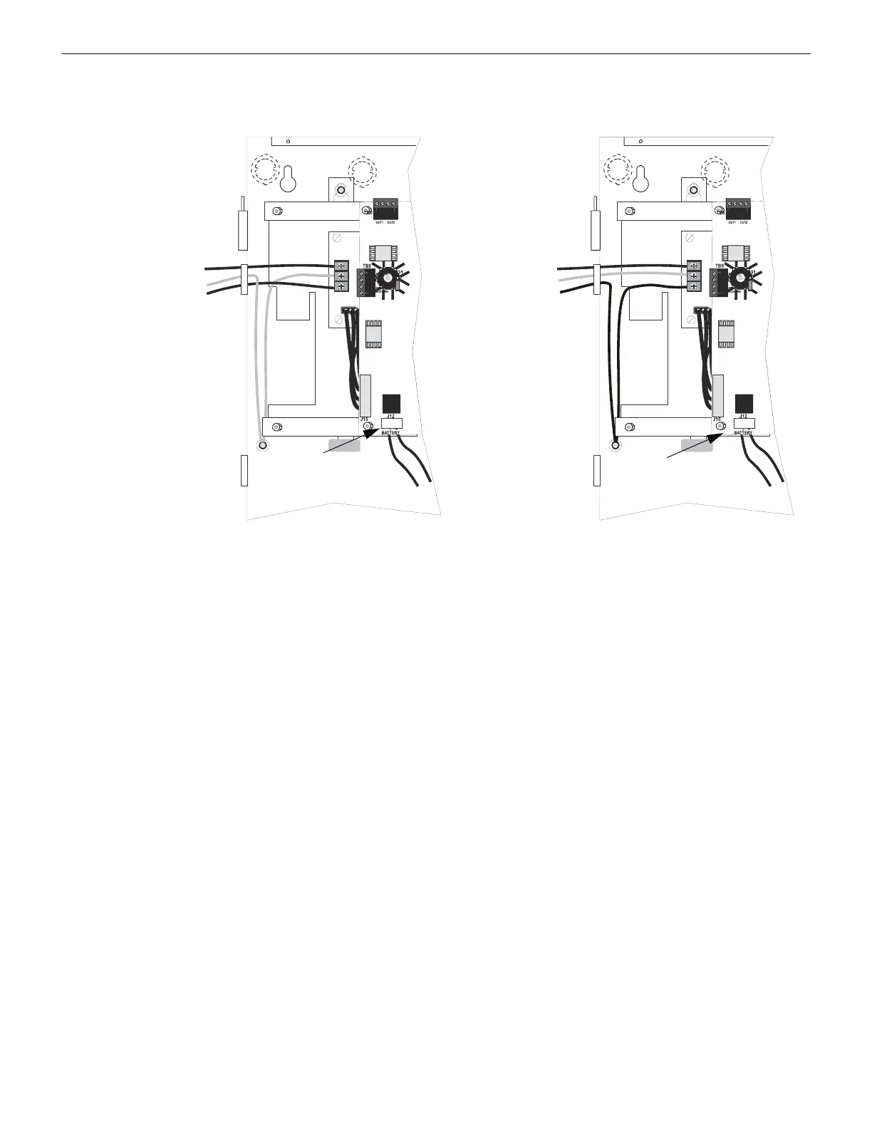
Figure 2.4 Operating Power Connections
AC Power
Hot (L1)
Earth
Neutral (L2)
Ground Stud
J12
to batteries
5ud_10udacpower.wmf
+
-
Ground Stud
J12
to batteries
+
-
FLPS-7
Power Supply
FLPS-3
Power Supply
AC Power
AC Hot
AC Neutral
Earth
MS-5UDC-7(C)(E)
MS-10UD-7(C)(E)
MS-5UD-3(E)
MS-10UD-3(E)

 Loading...


