34 MS-5UD & MS-10UD Series Manual — P/N 52626:C7 6/12/2018
Installation Installation of Optional Modules
Before installing the module, place the disconnect switch to the down (disconnect) position to prevent accidental activation of the munic-
ipal box. Note that a Disconnect LED will illuminate after the module is installed in the FACP. In addition, the System Trouble LED will
turn on to indicate the Disconnect condition.
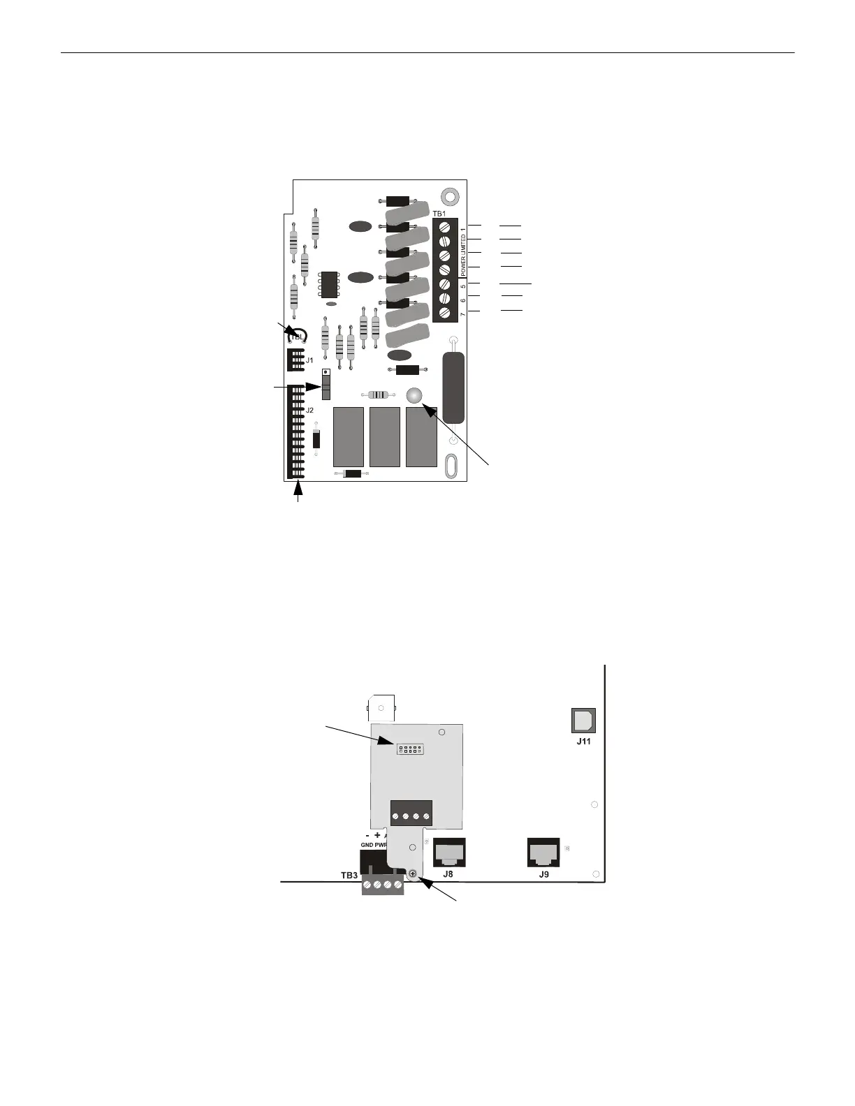
2.7.3 ANN-SEC Option Card
The ANN-SEC option card allows for a secondary ANN-BUS. Install the ANN-SEC as follows.
1. Remove the chassis mounting screw to the right of TB3 and replace it with the supplied 0.5” x 4-40 male-female standoff.
2. Install the header into J13 on the main circuit board.
3. Secure the ANN-SEC to the circuit board with the supplied screw.
Figure 2.17 4XTMF Transmitter Module
Connect to FACP Connectors J4 & J5
Disconnect
Switch
shown in
disconnect
position
TBL Jumper
}
Remote Alarm - Class 2
(power-limited)*
}
Remote Trouble - Class 2
(power-limited)*
No connection
1+
2-
3+
4-
5
6+
7-
Polarities are shown for module activation
Note: the 4XTMF Module is not directly suitable for transmitting reverse polarity supervisory signal.
For an application of reverse polarity of a supervisory signal, refer to the Appendix titled “FACP with
Keltron” on page 124.
* Wiring from these terminals
can exit the protected premises.
Dummy load terminals 6 and 7
(4.7KΩ, ¼ watt resistor) if
Municipal Box is not connected.
Disconnect LED
4xtmf.wmf
ANN-SEC
FACP Circuit Board
connector to J13 on
main circuit board
standoff and screw
Figure 2.18 Installing the ANN-SEC Option Card
ann-secinst.wmf

 Loading...


