MS-5UD & MS-10UD Series Manual — P/N 52626:C7 6/12/2018 125
Appendix D: Wire Requirements
Connecting external system accessories to the main circuits must be carefully considered to ensure proper operation. It is important to
use the correct type of wire, gauge and run length for each circuit. Reference the chart below to specify wire requirements and limitations
for each circuit.
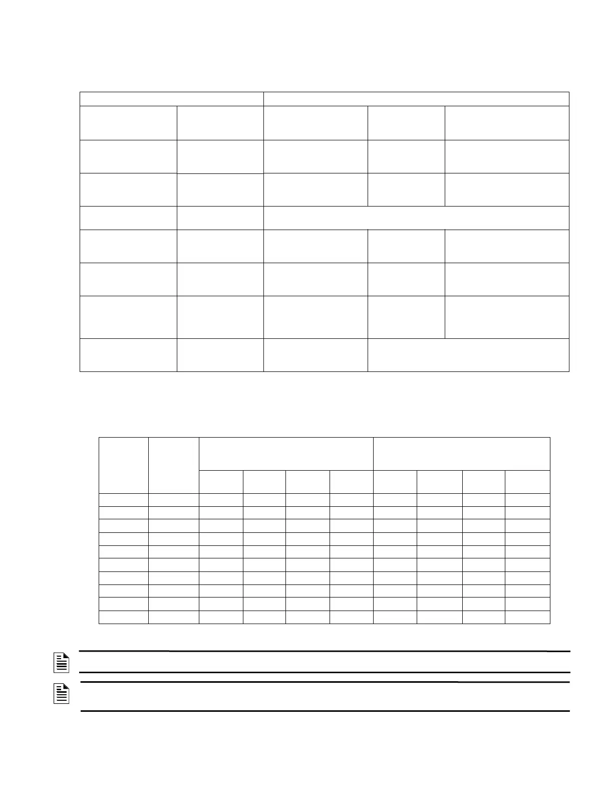
D.1 MS-5UD-3(E) & MS-10UD-3(E) NAC Wiring
The following table lists NAC wiring requirements for the MS-5UD-3(E) & MS-10UD-3(E) FACP which utilizes the FLPS-3 power
supply.
CIRCUIT CONNECTIONS WIRE REQUIREMENTS
Circuit Type Circuit Function
Wire Type and
Limitations
Recommended
Max. Distance
Feet (meters)
Wire Gauge
Initiating Device Circuit
(power-limited)
Connects to Initiating
Devices
Untwisted, unshielded wire
(maximum loop resistance
not to exceed 100 ohms)
Distance limitation
set by 100 ohm
resistance limitation
12-18 AWG (3.25 - 0.75 mm
2
)
ANN-BUS (EIA-485)
power-limited
Communication for
ANN-BUS annunciator
and relay modules
Twisted pair a maximum
loop resistance of 120
ohms
6,000 (1,800 m) 12-18 AWG (3.25 - 0.75 mm
2
)
ANN-BUS Power Power for ANN-BUS
annunciators
Refer to Table 2.2, “Wiring Distances,” on page 35 for information on device wiring
24 VDC Regulated,
resettable, nonresettable
Power for accessories
and 4-wire devices
Untwisted, unshielded wire Distance limitation
set by 4 volt
maximum line drop
12-18 AWG (3.25 - 0.75 mm
2
)
Auxiliary Trouble Input Open Collector trouble
input for CHG-75,
CHG-120F, etc.
Single conductor Distance limitation
20 feet in same
room
18 AWG (0.75 mm
2
)
Remote Sync Output Provides strobe and
normal sync for
remote NAC power
supplies
Untwisted, unshielded pair
wire
Distance set by 295
ohm resistance
limitation
12-18 AWG (3.25 - 0.75 mm
2
)
NAC Outputs Connects to NAC
devices or Release
devices
Untwisted, unshielded pair
wire
Refer to Section D.1 and Section D.2 on page 126.
Table D.1 FACP Wire Specifications
NAC Load
(Amps)
Max.
allowable
total loop
resistance
(ohms)
CLASS-B
Max. allowable wire pair length
(feet)
CLASS-A
Max. allowable wire pair length
(feet)
AWG 12
solid
AWG 14
solid
AWG 16
solid
AWG 18
solid
AWG 12
solid
AWG 14
solid
AWG 16
solid
AWG 18
solid
0.25 6.00 1554 977 613 386 777 489 307 193
0.5 3.00 777 489 307 193 389 244 153 97
0.75 2.00 518 326 204 129 259 163 102 64
1 1.50 389 244 153 97 194 122 77 48
1.25 1.20 311 195 123 77 155 98 61 39
1.5 1.00 259 163 102 64 130 81 51 32
1.75 0.86 222 140 88 55 111 70 44 28
2 0.75 194 122 77 48 97 61 38 24
2.25 0.67 173 109 68 43 86 54 34 21
2.5 0.60 155 98 61 39 78 49 31 19
Table D.2 NAC Wiring Requirements for FACP with FLPS-3 Power Supply
NOTE: Calculations are based on Direct-Current Resistance data for uncoated copper wire, per National Electrical Code (2005 Edition)
Table 8, Conductor Properties.
NOTE: These distances reflect the worst case scenario and are based on the current draw of the highest candela strobes at the low end
of the supported NAC voltage with the entire load at the end of the circuit. Further distances can be achieved by performing a point to point
voltage calculation that more accurately reflects the specific devices used and how they are dispersed on the circuit.

 Loading...


