MS-5UD & MS-10UD Series Manual — P/N 52626:C7 6/12/2018 111
Calculating the System Current Draw Power Supply Calculations
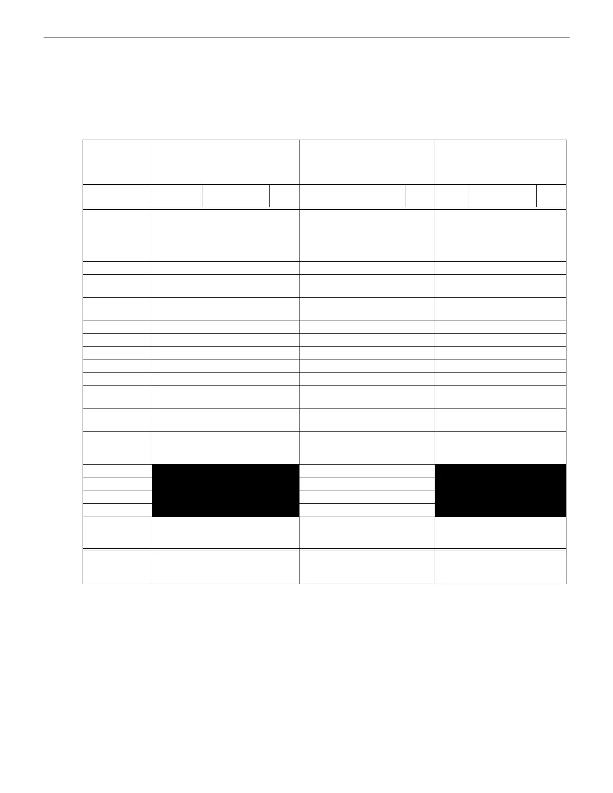
Calculation Column 1 - The primary supply current load that the control panel must support during a non-fire alarm condition,
with AC power applied.
Calculation Column 2 - The primary supply current load that the control panel must support during a fire alarm condition, with
AC power applied.
Calculation Column 3 - The standby current drawn from the batteries in a non-fire alarm condition during a loss of AC power.
Table 7.3 contains three columns for calculating current draws. For maximum output current availability per circuit and per panel, refer
to Section 1.2, “Specifications”, on page 13. For each column, calculate the current and enter the total (in amperes) in the bottom row.
When finished, copy the totals from Calculation Column 2 and Calculation Column 3 to Table 7.4 on page 112.
Device Type
Calculation Column 1
Primary, Non-Fire Alarm Current
(amps)
Calculation Column 2
Secondary, Fire Alarm Current
(amps)
Calculation Column 3
Secondary, Non-Fire Alarm
Current
(amps)
Qty
X[current
draw]=
Total Qty
X [current draw]
=
Total Qty
X[current
draw]=
Total
Main Circuit
Board
MS-5UD
or
MS-10UD
1 X[0.110]=
X[0.133]=
1 X[0.214]
1, 2
=
X[0.282]
1, 2
=
1 If using the Reverse Polarity Alarm output, add 0.005 amps; if using the Reverse Polarity Trouble output, add another 0.005 amps.
2 The current draw shown represents one zone (IDC) on the main circuit board in alarm. One zone consumes 0.040 amps.
1 X[0.110]=
X[0.133]=
CAC-5X [ ] X[0.001]= [ ] X[0.001]= [ ] X[0.001]=
4XTMF [ ]
1 max.
X[0.005]= [ ]
1 max.
X[0.011]
1
= [ ]
1 max.
X[0.005]=
ANN-SEC card [ ]
1 max.
X[0.003]= [ ]
1 max.
X[0.003]= [ ]
1 max.
X[0.003]=
ANN-80(C) [ ] X[0.037]= [ ] X[0.040]= [ ] X[0.015]=
ANN-I/O [ ] X[0.035]= [ ] X[0.200]= [ ] X[0.035]=
ANN-RLY [ ] X[0.015]= [ ] X[0.075]= [ ] X[0.015]=
ANN-(R)LED
3
3 An ANN-LED is supplied standard with the MS-5UDC and MS-10UDC.
[ ] X[0.028]= [ ] X[0.068]= [ ] X[0.028]=
ANN-S/PG [ ] X[0.045]= [ ] X[0.045]= [ ] X[0.045]=
2-wire Detector
Heads
[ ] X[ ]
4
=
4 Refer to the Device Compatibility Document for standby current.
[ ]
5
5 Enter the number of IDCs used minus one.
X[0.040]= [ ] X[ ]
4
=
4-wire Detector
Heads
[ ] X[ ]
4
= [ ]
5
X[0.040]= [ ] X[ ]
4
=
Power
Supervision
Relays
6
6 Must use compatible listed Power Supervision Relay.
[ ] X[0.025]= [ ] X[0.025]= [ ] X[0.025]=
NAC #1
[ ] X[ ]=
NAC #2 [ ] X[ ]=
NAC #3
NAC #4
Current Draw
from TB9
(nonalarm)
[ ]= [ ]= [ ]=
Sum each
column
7
for
totals
7 Total current draw listed above cannot exceed 3.25 amps for the MS-5UD-3(E), 3.28 for the MS-10UD-3(E), 7.25 for the MS-5UD-
7(C/E), and 7.28 for the MS-10UD-7(C/E).
Primary Non-Alarm = Secondary Alarm = Secondary Non-Alarm =
Table 7.3 System Current Draw Calculations

 Loading...


