68-0137B—2 6
F50F
PLANNING THE INSTALLATION
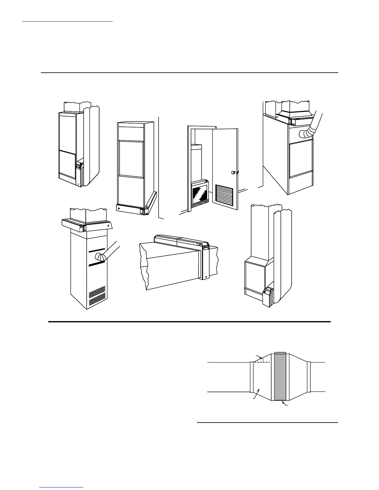
— Downflow “Counterflow” furnace: Air cleaner is
mounted horizontally in return duct or plenum just
above furnace. See Fig. 3E.
— High capacity system: Two or more air cleaners can
be used together. See Fig. 3F.
— Electric furnace or heat pump: Single cell air cleaner
is mounted with access door on top. See Fig. 3G.
Fig. 3—Mounting positions with variety of furnace installations.
M5628
A
B
C
D
E
F
G
DETERMINE DUCT DESIGN REQUIREMENTS
The air cleaner is adaptable to all new or existing forced
air heating, cooling and ventilating systems used in residen-
tial applications. Transitions, turning vanes, or offsets may
be needed in some applications for effective operation.
Transitions
Transitions are needed when the duct is a different
size than the air cleaner cabinet. Gradual transitions re-
duce air turbulence and increase efficiency. Limit ex-
pansion to no more than 20 degrees or about 4 in. per
running foot [100 mm per 300 linear mm] on each side of
a transition fitting. See Fig. 4.
Fig. 4—Change duct size gradually to minimize
turbulence.
20 DEGREE EXPANSION PER SIDE PER
FITTING (4 IN. PER RUNNING FOOT
[100 MM PER 300 LINEAR MM])
RETURN AIR
DUCT
TRANSITION FITTING
ELECTRONIC
AIR CLEANER CABINET
M5626
 Loading...