Do you have a question about the Honeywell Galaxy Flex 50 V3 and is the answer not in the manual?
Guidance on site selection for the control panel, considering power and communication requirements.
Steps for physically mounting the control panel and connecting the primary keypad.
Instructions for connecting the mains power supply and battery to the control panel.
Covers zone addressing, detector connection, and configuration for various zone types.
Guidance on safely connecting the backup battery and mains power supply.
Steps for the initial setup and configuration of the alarm system after power application.
Instructions for installing and connecting peripheral devices via data buses like RS485 and Intellibus.
Details on connecting devices to the RS485 data bus, including addressing and EOL resistors.
Guidance on connecting devices to the Intellibus, including auto-learn procedures.
Procedure for learning wireless sensors and keyfobs onto the system via an RF Portal.
Covers parameters, zone programming, output programming, communication, and timers.
Procedure for performing audible or silent walk tests on system zones.
Guides on testing system outputs like Bells and Strobes based on their function.
Tests up to two zones under full set conditions, including remote signalling.
Covers modifying PINs, user levels, names, groups, and card/fob assignments.
Lists the default Manager, Engineer, and Remote User PINs and user numbers.
Procedure to enter engineering mode for system programming and access.
Covers various methods for setting and unsetting the system, including PIN entry.
Step-by-step guide on how to set the system using a personal identification number.
Details on how to unset the system using a PIN, including group choice functionality.
Instructions for setting and unsetting the system using proximity cards, tags, or fobs.
Procedure for unsetting the system or groups using proximity cards.
Steps to cancel alarms, reset the panel, and manage system alerts.
How to override existing faults or tampers to allow system setting.
Enables system control via SMS messages sent to the GSM module.
Temporarily removes zones from the system without generating an alarm.
Allows viewing of the event log, which stores up to 1000 events.
Tests system zones by activating them and checking their response.
Tests system outputs based on their function, such as Bells or Strobes.
Allows modification of the system's time and date settings.
Manages user codes, card users, and RF batch learning for system access.
Manages weekly schedules, timer outputs, and autoset configurations.
Controls site-initiated remote connectors for system access and servicing.
Enables a manager to authorize an engineer to access the system.
Allows modification of system functions via parameter settings.
Sets the duration for bell activation on alarm events.
Delays full intruder alarm activation following an entry alarm.
Selects user types that can reset the system after an intruder alarm.
Selects user types that can reset the system after a tamper event.
Re-configures the system without removing power, useful after module changes.
Resets all system defaults back to factory settings.
Defines valid alarm cause codes for system reset, requiring user entry.
Sets the number of invalid code attempts before keypad lockout.
Menu structure for programming zones, including RF and Camera zones.
Assigns the zone type and function, allowing selection via reference number.
Learns multiple wireless detectors onto the system in a single operation.
Personal Attack function, overrides Bell Delay for an instant full alarm.
Continuously operational Fire zone that overrides Bell Delay for instant alarm.
Continuously operational Tamper zone that generates a tamper alarm when activated.
Defines output attributes like function, mode, polarity, descriptor, and group assignments.
Guides on selecting and programming outputs, including RIO, control panel, and keypad outputs.
Step-by-step instructions for selecting zones to be included in the soak test.
Controls messages transmitted to an Alarm Receiving Centre (ARC).
Configures receivers, reports, triggers, and IP check for ARC notifications.
Defines messages sent directly to end-user mobile phones via SMS.
Allows alterations to characteristics of different communication modules.
Controls remote site access by the remote operator via various modes.
Programs telephone numbers or IP addresses for remote servicing callback.
Controls remote panel access for integrating systems into building management.
Enables users to control the panel remotely via SMS.
Sets up audio transmission for alarm verification and live audio to ARC.
Verifies ARC reception via communication paths and tests all receivers.
Assigns individual attributes to keypads to control their response.
Access to diagnostic tests for communication, voltages, resistance, and modules.
Records minor failures and degradations to help trace intermittent faults.
Selects and tests up to two zones under full set conditions for alarm verification.
Procedure for initiating the full test by selecting zones.
Enables the Groups function, making group programming options available.
Allows customization of zone functions into Custom-A and Custom-B zones.
Details the 4 stages for assembling a custom zone: outputs, status, setting, and log.
Menu structure for managing weekly schedules, timer outputs, and autoset.
Programs timer schedules on a weekly basis, controlling panel functions.
Programs up to 42 Autoset events over a 7-day period per group.
Alerts user to zones that may not be operating correctly before system set.
Performs engineer reset authorized by ARC using a decoded number.
Assigns access types to menu options for different code types.
Menu for configuring MAX or Door Control modules for access control.
Programs MAX access control readers, including address and parameters.
Programs door control modules (DCMs) for access control readers.
Programs MAX access control readers, integrating them with the system.
Assigns and modifies MAX module addresses and their online/standalone status.
Defines operational features for each MAX module.
Programs door control module (DCM) access control readers.
Defines operational features for each DCM module.
Access to auto detect feature for recognizing system modules.
Lets the system automatically recognize new and removed modules.
Lists SIA and Contact ID event codes for alarm and status reporting.
Table showing nominal and alarm current draw for various system peripherals.
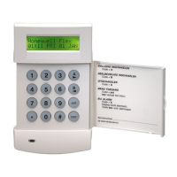
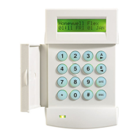
Details features, power consumption, and installation of MK8 Keypad/KeyProx.
Wireless interface for receiving signals from detectors and keyfobs.
Provides 8 programmable zones and 4 outputs, powered by 12 V d.c.
Connects to control panel for alarm signalling and remote servicing via mobile networks.
Instructions for programming the GSM or GPRS module via control panel menus.
Configures the module for GSM or GPRS channels via network menus.
Ensures a valid SIM card is installed and guides manual network programming if needed.
Interrogates GSM/GPRS connection status and checks diagnostic logs for faults.
Allows Intellibus panels to communicate via local and wide area networks.
Connects via RS485, offers graphical display and touch-screen control.
Steps for mounting the TouchCenter, including plate alignment and cable routing.
To configure a new TouchCenter by setting an address and repowering the panel.
Proximity reader access control for single doors, configurable as standalone or online.
Connects the MAX4 unit to the control panel in online or standalone configuration.
Configures MAX4 readers in engineer mode, setting online/standalone and addresses.
Details the two variants of the Power Supply Unit and Power RIO.
Steps for panel installation, routing mains cable, and wiring mains power.
Links two audio channels for alarm verification and live audio transmission.
Adds integrated access control to RS485 bus, controlling up to two readers.
Instructions for installing and mounting the DCM PCB in RIO or Power RIO boxes.
Connects wires from the Reader to the Wiegand Reader Inputs on the DCM.
Configures DCM on panel power up or engineer mode exit, indicating status via LEDs.
Provides alarm verification by capturing images from Camera PIRs.
| Brand | Honeywell |
|---|---|
| Model | Galaxy Flex 50 V3 |
| Category | Security System |
| Language | English |