Do you have a question about the Honeywell Gamewell FCI ILI-MB-E3 and is the answer not in the manual?
| Manufacturer | Honeywell Gamewell FCI |
|---|---|
| Model | ILI-MB-E3 |
| Category | Motherboard |
| Compatibility | E3 Series |
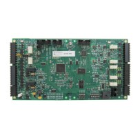
| Description | Main Motherboard for E3 Series Fire Alarm System |
Details the various cabinet options and their typical configurations for the E3 Series system.
Step-by-step instructions for installing the Cabinet A1 backbox, including mounting site preparation.
Instructions for attaching the inner door to the backbox, including spacer and bonding wire installation.
Step-by-step instructions for installing the Cabinet A2 backbox, including mounting site preparation.
Instructions for attaching the inner door to the backbox, including spacer and bonding wire installation.
Step-by-step instructions for installing the backbox for the flush annunciator, including mounting site prep.
Instructions for mounting the keyswitch, LCD-E3 keypad, and front cover to the backbox.
Step-by-step instructions for installing the backbox for Cabinet A or AA, 2-Bay and 3-Bay configurations.
Instructions for attaching the 2-Bay inner door to the backbox, including spacer and bonding wire.
Instructions for attaching the 3-Bay inner door to the backbox, including spacer and bonding wire installation.
Step-by-step instructions for installing the Cabinet B backbox, including mounting site preparation and knockouts.
Instructions for mounting ILI-MB-E3/ILI95-MB-E3, DACT-E3/RPT-E3, and PM-9/PM-9G onto the backbox.
Instructions for attaching the inner door to the backbox, including spacer and bonding wire installation.
Step-by-step instructions for installing the B-Slim Cabinet backbox, including mounting site preparation.
Instructions for mounting ILI-MB-E3/ILI95-MB-E3 and PM-9/PM-9G onto the B-Slim-E3 Plate.
Instructions for mounting the B-Slim-E3 sub-assembly plate onto the studs in the backbox.
Step-by-step instructions for installing the Cabinet C backbox, including mounting site preparation.
Instructions for mounting various modules (ILI, DACT, RPT, PM-9, INI-VG, AM-50) onto the E3-INX-C Plate.
Instructions for mounting the E3-INX-C sub-assemblies plate onto the studs in the backbox.
Instructions for mounting modules (ILI, DACT, RPT, PM-9, INI-VG) onto the E3-INCC-C Plate.
Instructions for mounting the E3-INCC-C sub-assembly plate onto the studs in the backbox.
Instructions for mounting modules (ILI, DACT, RPT, PM-9) onto the E3-ILI-C Plate.
Instructions for mounting the E3-INCC-C or E3-ILI-C plate and AM-50 Extender Plate to the backbox.
Instructions for mounting sub-assembly plates and FPT-GATE-3 Extender Plate onto backbox studs.
Instructions for attaching the 7-Bay inner door to the backbox, including spacer and bonding wire.
Instructions for attaching the 8-Bay inner door to the backbox, including spacer and bonding wire installation.
Step-by-step instructions for installing the Cabinet D backbox, including mounting site preparation.
Instructions for mounting modules (ILI, DACT, RPT, PM-9, INI-VG, AM-50) onto the E3-INX-D Plate.
Instructions for mounting modules (ILI, DACT, RPT, PM-9, INI-VG) and multiple ILI modules onto the E3-INCC-D Plate.
Instructions for mounting the E3-INCC-D sub-assembly plate onto the studs in the backbox.
Instructions for attaching the 13-Bay inner door to the backbox, including spacer and bonding wire.
Instructions for attaching the 14-Bay inner door to the backbox, including spacer and bonding wire installation.
Details electrical specifications and wiring for the ILI-MB-E3 and ILI95-MB-E3 main boards.
Details the two 24 VDC Class A/B signaling line circuits provided by ILI-MB-E3/ILI95-MB-E3.
Details connections and wiring for the ILI-MB-E3 main board.
Provides detailed field wiring connections for the ILI-MB-E3, covering terminal designations and comments.
Illustrates the field wiring connections for the ILI-MB-E3 sub-assembly with diagrams and notes.
Details connections and wiring for the ILI95-MB-E3 main board.
Details field wiring connections for the ILI95-MB-E3, including terminal designations and comments.
Illustrates the field wiring connections for the ILI95-MB-E3 sub-assembly with diagrams and notes.
Lists field wiring connections for the ILI-S-E3, including designation, description, and comments.
Illustrates the field wiring connections for the ILI-S-E3 sub-assembly with diagrams and notes.
Lists field wiring connections for the ILI95-S-E3, including designation, description, and comments.
Illustrates the field wiring connections for the ILI95-S-E3 sub-assembly with diagrams and notes.
Lists field wiring connections for the ANX-SR sub-assembly, including terminal designations and comments.
Illustrates the field wiring connections for the ANX-SR sub-assembly with diagrams and notes.
Lists field wiring connections for the ANX-MR-UTP, including terminal designations and comments.
Illustrates the wiring diagram for the ANX-MR-UTP sub-assembly with diagrams and notes.
Lists field wiring connections for the ANX-MR-FO, including terminal designations and comments.
Illustrates the wiring diagram for the ANX-MR-FO sub-assembly with diagrams and notes.
Details power supply connections, including AC power and battery connections.
Details AC power connection requirements for PM-9 and PM-9G, emphasizing compliance with NEC and NFPA standards.
Lists field wiring connections for the PM-9 power supply, including terminals, jumpers, and LEDs.
Illustrates the wiring diagram for the PM-9 sub-assembly with connection details and notes.
Lists field wiring connections for the PM-9G power supply, including terminals, jumpers, and LEDs.
Illustrates the wiring diagram for the PM-9G sub-assembly with connection details and notes.
Details wiring connections for ASM-16, ANU-48, INI-VG, ILI-MB-E3/ILI95-MB-E3, and LCD-E3.
Illustrates wiring connections between ASM-16, ANU-48, and other system modules via ribbon cable and RS-485.
Illustrates the field wiring connections for the ASM-16 module with diagrams and notes.
Lists the DACT-E3 wiring connections for the TB1 and TB2 terminals.
Illustrates the field wiring connections for the DACT-E3 with diagrams and LED status indications.
Lists field wiring connections for the RPT-E3, including terminal designations and comments.
Illustrates the field wiring connections for the RPT-E3 with diagrams and LED status indications.
Lists field wiring connections for the ANU-48, including terminal designations and comments.
Illustrates the field wiring connections for the ANU-48 with diagrams and notes.
Lists field wiring connections for the LCD-E3, including terminal designations and comments.
Illustrates the field wiring connections for the LCD-E3 with diagrams and notes.
Lists field wiring connections for the LCD-7100, including terminal designations and comments.