Do you have a question about the Honeywell KTR 2280A and is the answer not in the manual?
Regulations governing the export and re-export of the product.
Terms and conditions for using Honeywell's proprietary materials.
Overview of the KTR 2280A MMDR, installation, and airworthiness approval.
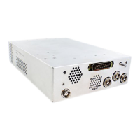
Detailed description of the KTR 2280A MMDR transceiver and its capabilities.
Key technical specifications and characteristics of the KTR 2280A MMDR.
General suggestions and information for optimal KTR 2280A installation.
Procedures for carefully unpacking and inspecting the KTR 2280A for damage.
Guidelines and procedures for installing the KTR 2280A system components.
Instructions on how to use the manual for maintenance and procedures.
Emphasizes adherence to safety, quality, and operational procedures.
Explanation of symbols and special characters used in the manual.
Information on accessing Honeywell's online technical publications.
Contact details for Honeywell Aerospace customer support.
List of Honeywell and vendor publications relevant to the manual.
List of standard reference publications used in the manual.
Explains the use of abbreviations and acronyms according to standards.
Overview of the KTR 2280A MMDR, installation, and airworthiness approval.
Detailed description of the KTR 2280A MMDR transceiver and its capabilities.
Key technical specifications and characteristics of the KTR 2280A MMDR.
Technical specifications for the KA 44B antenna.
List of units and accessories included with the KTR 2280A installation kit.
Details of the parts included in the KTR 2280A installation kit.
List of accessories necessary for installation but not included.
Information regarding FCC approvals and licensing requirements.
Instructions for maintaining continued airworthiness of the equipment.
Safety precautions regarding RF exposure from antenna installation.
General suggestions and information for optimal KTR 2280A installation.
Procedures for carefully unpacking and inspecting the KTR 2280A for damage.
Guidelines and procedures for installing the KTR 2280A system components.
Information on selecting appropriate locations for KTR 2280A components.
Procedures for the mechanical installation of the KTR 2280A unit.
Procedures for mechanically installing antennas for the KTR 2280A.
Specific guidelines for mounting VHF COM antennas.
Specific guidelines for mounting NAV antennas.
Specific guidelines for mounting ADF antennas.
Procedures for wiring and installing cables for the KTR 2280A.
Instructions for fabricating interconnections and cable harnesses.
Instructions for assembling and installing Taylor backshells.
General information about Taylor backshells and their purpose.
Requirements for primary power connections and circuit breakers.
Information on the connectors used with the KTR 2280A.
Information on recommended crimp tools and accessories.
Procedures for performing post-installation checks and inspections.
Detailed inspection and ground test procedures for the MMDR.
Visual inspection steps for the equipment and antennas.
Ground testing procedures for NAV/COM and ADF functionality.
Ground check for NAV and COM functions before flight tests.
Preliminary check for ADF functionality using local stations.
Flight test procedures to verify system operation after installation.
Flight testing the COM transceiver with a ground station.
Flight testing the NAV receiver with VOR and ILS signals.
Flight testing the ADF receiver by checking bearing indications.
Procedures for adjusting installation parameters for the KTR 2280A.
Information on ARINC 429 transmitters and receivers used by the KTR 2280A.
Overview of the KTR 2280A's remote operation interface.
Description of VHF COM controls and displays available in the system.
Description of VHF NAV controls and displays available in the system.
Description of ADF controls and displays available in the system.
Explanation of VDL Mode A and VDL Mode 2 capabilities.
Forms related to the environmental qualification of the KTR 2280A.
The formal environmental qualification form for the KTR 2280A.
Environmental qualification form based on RTCA DO-160G and EUROCAE ED-14G.
Environmental performance testing results for the KA 44B ADF Antenna.
Results of RF susceptibility testing for the KA 44B antenna.
Results of lightning transient susceptibility tests for the KA 44B antenna.
Results of lightning direct effects tests for the KA 44B antenna.
Section detailing deviations from standard requirements for the KTR 2280A.
Deviation for receiver rejection specification related to TSO-C41d.
Deviation for VDB receiver subsystem performance requirements.
Deviation to reduce out-of-band interferer levels for VHF FM broadcast signals.
Use of RTCA/DO-160G for environmental qualification instead of obsolete versions.
Use of RTCA/DO-178B for software qualification instead of obsolete versions.
Honeywell's submitted deviation requests for ETSO approvals.
Deviation for receiver frequency range specification for ETSO-2C41d.