EasyManua.ls Logo

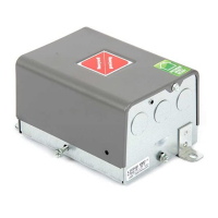
Honeywell L7224C - User Manual

Honeywell L7224C
16 pages
To Next Page IconTo Next Page
Loading...
INSTALLATION INSTRUCTIONS
68-0281-16
L7224A,C; L7248A,C,L
Oil and Electric Boiler
Electronic Aquastat
®
Controllers
APPLICATION
The L7224A,C and L7248A,C,L 2012 Compliant
Electronic Aquastat
®
Controllers provide electronic
temperature sensing in a UL limit-rated control with a
single sensing probe. The L7224A,C and L7248A,C,L
control the circulator, oil or electric burner or contactor,
and boiler temperature. The L7224/L7248 is “Outdoor
Temperature Reset” ready which is enabled when
connected to the W8735Y1000 wireless or W8735S1000
wired Outdoor Reset Kit. Outdoor Reset with the L7224/
L7248 is intended for all applications except for tankless
coil systems for domestic hot water. Compliance to 2012
DOE regulation ensures efficiency is maximized without
interfering with domestic hot water demand.
The L7224A,C and L7248A,C,L replace the L8124A,
L8124C, L7124A,C, L7148A and L8148A Controllers.
The L7224A,C and L7248A,C,L series controls provide
status and diagnostic information through an LED display
combined with LED lights as well as EnviraCOM™
communications enabled thermostats and diagnostic
tools to enhance the diagnostic process.
L7224/L7248 Aquastat Controllers are intended for use
in residential-type applications.
IMPORTANT
Use of Outdoor Temperature Reset on a tank-
less coil application requiring a Low Limit setting
will result in reduced system effectiveness and
efficiency.
SPECIFICATIONS
Electrical Ratings:
Voltage: 120 Vac, 60 Hz.
Power: 7 VA maximum at 120 Vac plus external loads.
Thermostat current: 100 mA nominal at 24 Vac.
Burner Relay:
7.4 A at 120 Vac Full Load Amperage (FLA);
44.4 A inrush Locked Rotor Amperage (LRA);
Less Ignition Load: 360 VA.
Circulator Relay:
7.4 A at 120 Vac FLA; 44.4 A inrush LRA.
Zone Controller (ZC): 7.4 A at 120 Vac FLA;
44.4 A inrush LRA.
NOTE: All loads combined cannot exceed 2000 VA.
Environmental Ratings:
Temperature: -30 °F to +150 °F (-34 °C to +66 °C).
Humidity: 0 to 95% relative humidity, noncondensing.
Approvals:
Underwriters Laboratories Inc. Component Recognized.
Canadian Underwriters Laboratories Inc. Component
Recognized.
2012 DOE Compliance and Operation
Operation of this control may delay the burner operation while the residual heat is
circulated out of the boiler.
NOTE: This operation may be different than earlier electronic Aquastat
®
revisions which did not implement thermal purge.

Questions and Answers:

Honeywell L7224C Specifications

General IconGeneral
Voltage24V AC
Frequency60 Hz
Switch ActionSPDT
ApprovalsUL, CSA
Control TypeOn/Off
MountingSurface
IgnitionIntermittent Ignition
Flame Failure Response Time0.8 seconds
Prepurge Time60 seconds

Summary

Product Application Overview

General Application and Compatibility

Describes the general use, compatibility, and features of the electronic Aquastat controllers.

Installation and Specifications

Installation Instructions and Important Notes

Provides initial installation guidance, safety warnings, and important notes for setup.

Controller Specifications

Details electrical ratings, environmental ratings, and agency approvals for the Aquastat.

2012 DOE Compliance and Thermal Purge

Explains 2012 DOE regulation compliance and thermal purge operation.

Detailed Installation and Wiring

Mounting the Aquastat Controller

Covers mounting options, dimensions, and the importance of sensor fit in the well.

New Installation Procedures

Step-by-step instructions for installing a new Aquastat controller and its components.

Replacement Sensor Installation

Detailed guide for removing and installing a replacement sensor element.

Wiring Safety and Guidelines

Provides critical safety warnings and general wiring guidelines for the controller.

Operation and Settings Configuration

Adjustable Features and Parameters

Lists and defines adjustable features like High Limit, Low Limit, and differentials.

How to Adjust Aquastat Settings

Procedure for entering adjustment mode and modifying controller settings.

Understanding the Controller Display

Explains the controller's display modes and how to read status information.

System Control Logic and Features

High Limit Control Operation

Details how the High Limit function operates to control burner and circulator.

Low Limit and Circulator Control

Explains the operation of the Low Limit and its interaction with the circulator.

Anti Short-Cycle Protection

Describes the function and purpose of the anti short-cycle delay feature.

Specialized Operational Modes

Frost Protection Functionality

Details the Frost Protection feature to safeguard against freezing.

Thermal Purge Operation and Settings

Explains thermal purge operation and its configurable settings.

Pump Cycling for System Maintenance

Describes the pump cycling feature for periodic system exercise.

Wiring Diagrams for Various Systems

Single Zone System with Modules Wiring

Illustrates wiring for single zone systems with optional Outdoor Reset and DHW modules.

Multizone System Wiring Examples

Shows wiring configurations for multizone systems with circulator connections.

External Low Limit Wiring

Diagrams the wiring for external low limit connections on the L7248L model.

Troubleshooting and Diagnostics

Understanding LED Error Codes

Lists and defines LED error codes for diagnosing system faults.

Troubleshooting Common Issues

Provides a guide to diagnose and resolve common system conditions and errors.

Related product manuals