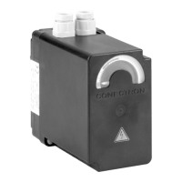
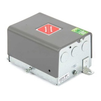
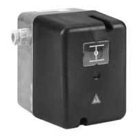
LKS 310 Actuator for air dampers on multi-stage and modulating burners
2 www.honeywell.com
DESCRIPTION
A synchronous motor powers an output shaft and a backlashfree
cam shaft via a gear reducer.
The cam shaft operates limit and auxiliary switches. The position
at which one of the limit or auxiliary switches operates can be ad-
justed steplessly within the operating range using the associated
cam disc. Manually adjustable lever-operated cams or spindle-
driven cams, which can be adjusted with a screwdriver, are avail-
able.
FEATURES
Electric actuator up to 15 Nm
• Drive times: 3.5 ... 30 sec.
• Gearing can be decoupled
• Position indicator
• Easily adjustable limit and auxiliary switches
• Synchronous motor
• Particulary stable design in aluminium housing
Variants:
• clockwise or counter clockwise rotation
• with integrated electronic circuitry
• different shaft versions
SPECIFICATION
Type overview
Clockwise rotation
1)
Counter-clockwise rotation
1)
Legende
1) when viewing from direction A (see dimensional drawing)
2) see “Circuit diagrams”
3) see “Shaft versions”
4) at 50 Hz for 90°
at 60 Hz, Drive times are about 20 % shorter
5) under nominal conditions
under extreme conditions (e.g. +60 °C, 230V -15%) the torques will be 25% lower
6) +10% -15%; 50...60Hz
at -15%; torque reduced by approx. 20% at undervoltage
7) Standard: Lever-operated cam
Diagram
2)
Shaft
3)
Drive
time
4)
Load
torque
5)
Holding
torque
Voltage
6)
Type Remarks
7)
Nr. Nr. s Nm Nm V
S1 5D 30 15 10 230 LKS 310-15 (A-5D-30 S1) Spindle-driven cam
S12 5D 30 15 10 230 LKS 310-21 (A-5D-30 S12) Spindle-driven cam
S7 5B 30 15 10 230 LKS 310-22 (A-5B-30 S7)
S7 5B 10 10 10 230 LKS 310-24 (A-5B-10 S7.1)
S7 5B 15 15 10 230 LKS 310-25 (A-5B-15 S7.1)
S12 5D 7 7 7 110 LKS 310-34 (A-5D-7 S12.1) Spindle-driven cam
S7 5C 30 15 10 230 LKS 310-35 (A-5C-30 S7) IP54
Diagram
2)
Shaft
3)
Drive
time
4)
Load
torque
5)
Holding
torque
Voltage
6)
Type Remarks
7)
Nr. Nr. s Nm Nm V
S8 5A 3,5 3,5 3,5 230 LKS 310-10 (B-5A-3.5 S8)
S7 5C 3,5 3,5 3,5 230 LKS 310-17 (B-5C-3.5 S7.1)
S7 5B 15 15 10 230 LKS 310-31 (B-5B-15 S7.1)
S7 5B 10 10 10 230 LKS 310-32 (B-5B-10 S7.1)
EN1C-0114SZ20 R0506