30 www.honeywell.com
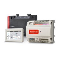
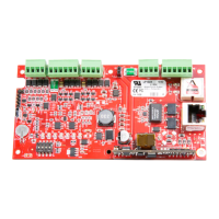
PW7K1ICE Wiring and Setup
Specifications
• Note: For UL installations, PoE powered devices shall not
be used. Power for these devices must be provided by an
UL 294-listed source (12VDC). This conflicts with the
information in PWLP1501_INSTALL.PDF which states the
PoE is acceptable to meet UL-294B.
• PoE power is to be supplied by a Listed ITE or Access
Control System Unit (ALVY), power limited, PoE+
injector or PoE+ Ethernet switch providing 42.5 – 57
VDC, 25.5W for maximum output.
SRAM Backup
Battery
• Rechargeable battery
Micro SD Card
• Format micro SD or SDHC;2-
8 GB
Host
Communica-
tion
• Ethernet: 10BaseT/100Base-TX and Micro USB port (2.0) with
optional adapter: pluggable model USB2-OTGE100
Inputs • 2 supervised, Programmable End of Line resistors, 1k/2k - ohm 1% 1/
4W watt standard, and dedicated tamper input
Relays • 2 outputs, Form-C contacts: 2A @ 30VDC
Reader Interface
Reader Power: • PoE: 12 VDC 10% or local
power supply (12VDC) (PTC
limited 300mA max)
Reader Data Inputs • Two TTL reader ports or one 2-
wire RS-485 reader port capable
of supporting two readers
compatible or F/2F
RS-485 Mode • 9600 bps
• Asynchronous
• Half-duplex
• 1 start bit
• 8 data bits
• 1 stop bit
• Maximum cable length: 4000'
(1,200m)
LED Output • TTL compatible
• High > 3V
• Low < 0.5V
• 5mA source/sink maximum
Buzzer Output • Open collector
• 12VDC open circuit maximum
• 40mA sink maximum
Cable requirements
 Loading...