SERIES 90 MODUTROL IV
™
MOTORS
63-2631—07 10
SETTINGS AND ADJUSTMENTS
Before Setting Stroke
1. Remove the top cover from the motor.
2. Disconnect the controller from the motor.
3. Connect a remote potentiometer to the motor as shown
in Fig. 6 (R-W-B).
The stroke adjustment on the series 2 and series 3 motors is
made using the stroke and sensitivity
potentiometers located
under the cove inside the motor. The stroke adjustment on a
series 1 motor was made by adjusting the CAMS.
For Series 2 and Series 3 Motors:
To set the stroke to 160 degrees (maximum position) turn both
stroke and sensitivity potentiometers fully clockwise ,
using a 1/8 inch straight-blade screwdriver.
To set the stroke to 90 degrees (minimum position) turn both
stroke and sensitivity potentiometers fully counter-clockwise
, using a 1/8 inch straight-blade screwdriver.
To set the stroke between 90 and 160 degrees:
1. Turn the stroke and sensitivity
potentiometers fully
clockwise, using a 1/8 inch straight-blade screwdriver.
2. Turn the remote
potentiometer (previously installed on
R-W-B terminals) to maximum position.
3. Turn the sensitivity potentiometer to the selected stroke
(between 90 and 160 degrees) OR until the motor stops.
4. IF the motor stops before the selected stroke is reached,
turn the stroke
potentiometer until the selected stroke is
reached OR
5. IF the selected stroke is reached using the sensitivity
potentiometer, turn the stroke
potentiometer counter-
clockwise until the motor begins to move. Then
turn the stroke
potentiometer clockwise slightly to
have the position correspond to the sensitivity
potentiometer.
6. Make sure the minimum position is correct.
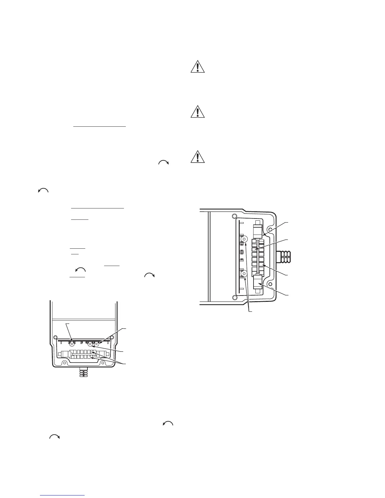
Fig. 10. Potentiometer Location and Stroke Adjustment
Setup for Non-Spring Return Series 90 Motors.
Adjustable timing for M9182D1023
The timing potentiometer (the second from the right, (Refer to
Fig. 10) sets the timing to 1minute, if turned fully CCW , 2
minutes if turned to its middle point and 4 minutes if turned fully
CW .
Equipment Damage Hazard.
Can damage the motor beyond repair.
Set cams by moving the top of the screwdriver only.
Pressing screwdriver against cam slot sides or use of
excessive force can damage motor end switches.
Fig. 11. Terminals and Adjustments.
Auxiliary Switches
Adjustable cams actuate the auxiliary switches. These cams
can be set to actuate the switches at any angle within the
stroke of the motor. Select switch differential of 1° or 10°.
Motors with factory-added auxiliary switches are shipped in the
closed position (fully counterclockwise, as viewed from the
power end). Auxiliary cam default actuates the switches 30°
from full open with a 1° differential. With the motor in the closed
(fully counterclockwise) position, the auxiliary switch breaks
contacts R-B. Refer to Fig. 7 (or the auxiliary switch Instruction
Sheet) for auxiliary switch wiring.
NOTE: Auxiliary switches can only be added to motors
that include auxiliary switch cams. (These cams
cannot be field-added.)
 Loading...