EasyManua.ls Logo

Honeywell M9484 User Manual

Honeywell M9484
12 pages
To Next Page IconTo Next Page
Page #1 background imageLoading...
Page #1 background image
Honeywell
M9484 AND M9494 MODUTROL MOTORS ARE LOW
VOLTAGE, REVERSING PROPORTIONAL CONTROL
ACTUATORS FOR VALVES, DAMPERS AND AUXIL-
IARY EQUIPMENT. THEY ARE ESPECIALLY DE-
SIGNED
FORCOMMERCIALOR
INDUSTRIALOILOR
GAS BURNER CONTROL SYSTEMS.
•i Replace M941 motors.
0
Oil immersed motor and gear train for reliable per-
formance and long life.
0
Wiring box provides NEMA 3 weather protection.
0
Actuator motor and circuitry operate from 24 volts
AC. Models available with factory installed transformer,
or internal transformer can be field added.
Cl
Quick-connect terminals standard
-
screw terminal
adapter available.
Cl
Adapter bracket for matching shaft height of older
motors is standard with replacement motors.
0
Field adjustable stroke (90” to 160’) models avail-
able.
q
Nominal timing of 30 seconds for 90” and 60 sec-
onds for
160”
stroke is standard. Other timings are
available.
0
Die-cast magnesium housing.
q Available accessories include valve and damper
linkages, explosion proof housing, and auxiliary
,
switches.
0
Field addable interface modules can be mounted in
wiring box to upgrade actuator to Series 70 (electronic)
control.
•i
Models available with tapped output shaft.
0
M9481,
M9484 rated for 150 lb.-in. torque at stan-
dard timings.
cl
M9491,
M9494 rated for 300 lb.-in. torque at 2 or 4
minute timings for
160“
stroke.
S.M.
Form Number 63-2195-l
Rev. 11-90
@Honeywell Inc. 1990
Question and Answer IconNeed help?

Do you have a question about the Honeywell M9484 and is the answer not in the manual?

Honeywell M9484 Specifications

General IconGeneral
BrandHoneywell
ModelM9484
CategoryEngine
LanguageEnglish

Summary

MODUTROL IV Motors Introduction

Product Overview and Applications

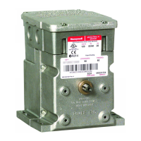
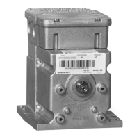
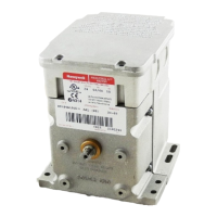
Introduces M9484/M9494 motors for burner control systems.

Key Product Features

Highlights oil-immersed gearbox, NEMA 3 wiring, adjustable stroke, die-cast housing.

Motor Specifications

Model Coding and Standard Options

Explains model nomenclature and standard features like stroke adjustment.

Electrical Ratings and Performance

Details voltage, current, power consumption, timing, and torque specs.

Load, Temperature, and Shaft Details

Covers load capacity, ambient temperature limits, and crankshaft specs.

Ordering Information

Contacting Sales and Customer Service

Provides contact details for local sales offices and customer service.

Accessories and Timing

Available Accessories

Lists optional accessories like explosion-proof housing and linkages.

Motor Timing Specifications

Details timing for 90°/160° strokes and breakaway torque.

Installation and Safety Precautions

Installation Guidelines

General steps for installing the Modutrol IV motor.

Important Safety Cautions

Critical warnings for safe installation and operation.

Mounting and Location

Recommended Mounting Locations

Advises on suitable locations, avoiding corrosive/explosive atmospheres.

Mounting Procedures

Details motor mounting, including crankshaft orientation.

Adapter Bracket and Linkage Mounting

220738A Adapter Bracket Use

Explains the purpose and mounting of the 220738A adapter bracket.

Damper Linkage Installation

Guidance on connecting motor to damper linkages.

Valve Linkages and Wiring

Valve Linkage Requirements

Specifies linkages needing adapter bracket for valve applications.

Wiring Connections and Safety

Covers wiring safety, transformer needs, and terminal connections.

Internal Wiring and Adjustments

Internal Wiring Diagrams

Shows internal wiring schematics for the motor.

Terminals and Adjustment Points

Identifies motor terminals and adjustment points like stroke potentiometers.

Auxiliary Switches and Stroke Setting

Auxiliary Switch Wiring and Color Coding

Explains wiring colors and connections for internal auxiliary switches.

Stroke Setting Procedure

Step-by-step guide for setting motor stroke (90° to 160°).

Stroke and Auxiliary Switch Adjustment Setup

Stroke Adjustment Setup Diagram

Illustrates the setup for adjusting motor stroke.

Auxiliary Switch Adjustment Setup Diagram

Illustrates the setup for adjusting auxiliary switch cams.

Operation, Control Circuits, and Troubleshooting

Modulating Series 90 Circuit Operation

Explains motor operation with Series 90 controllers.

Auxiliary Switch Setting Procedure

Detailed steps for setting auxiliary switches for desired differentials.

Connection Diagrams

Series 90 Controller Connections

Shows wiring for Series 90 controllers.

4-20 mA Control Connections

Illustrates wiring for 4-20 mA control outputs.

Checkout and Change-Out Procedures

Installation Checkout Steps

Procedures to verify correct installation and operation.

Actuator Change-Out Instructions

Guides for replacing actuators with new motors.

Related product manuals