EasyManua.ls Logo

Honeywell MICRONIK 200 R7426A User Manual

Honeywell MICRONIK 200 R7426A
20 pages
To Next Page IconTo Next Page
Page #1 background imageLoading...
Page #1 background image
HONEYWELL
Copyright © 2007 Honeywell GmbH All Rights Reserved EN1B-0203GE51 R0507C
R7426A,B,C
TEMPERATURE CONTROLLER
WITH AND WITHOUT REAL-TIME CLOCK
INSTALLATION & START-UP INSTRUCTIONS
Fig. 1. Temperature Controller
Contents
General................................................................................ 1
Before Installation Note ....................................................... 1
Mounting.............................................................................. 1
Wiring .................................................................................. 2
Power Supply and Grounding.............................................. 2
Configuration and Control Parameters ................................ 3
Configuration Settings ......................................................... 6
Parameter Settings and Adjustment .................................... 8
Operating Overview............................................................11
Notes (with RTC, only)....................................................... 19
GENERAL
This document provides instructions and procedures for
installing and starting up the Micronik 200 R7426A,B,C
controllers. No special tools are required for mounting and
installation. The user interface and liquid-crystal display allow
accurate and easy parameter setting and output adjustment.
BEFORE INSTALLATION NOTE
Visually inspect equipment for shipping damage.
Report any damage to the appropriate Honeywell
representative.
Refer to job drawings for specific installation
information and mounting location.
Verify the controllers will be adequately separated
from the main power supply, relays, or other equip-
ment which can possibly generate electromagnetic
interference.
Verify that the ambient temperature and the humidity
at the controllers will not exceed 0...50°C (32...122°F)
and 5 to 95% rh.
Use shielded wiring in areas with high EMI.
All wiring should be separated from power lines by at
least 150 mm (6’’).
Do not install controllers near frequency converters
or other high-frequency sources.
MOUNTING
The controllers can be mounted in an electric cabinet or other
suitable enclosure. They are suitable for back panel, DIN rail,
wall, or front panel mounting. The corresponding mounting
sequence, as well as dimensions and panel cut-out, are
illustrated in the mounting instruction sheet EN1B-0202GE51
supplied with the controllers.
If the compensation sensor signal (T3) is received from
another controller (parallel connection of compensation
sensor inputs), the jumper W303 has to be cut before
mounting the controller (see Fig. 2). This disconnects the
sensor from the internal power supply.
MicroniK 200
Question and Answer IconNeed help?

Do you have a question about the Honeywell MICRONIK 200 R7426A and is the answer not in the manual?

Honeywell MICRONIK 200 R7426A Specifications

General IconGeneral
BrandHoneywell
ModelMICRONIK 200 R7426A
CategoryTemperature Controller
LanguageEnglish

Summary

General Installation and Operation

Before Installation Checks

Important checks and conditions before installing the controller.

Mounting Guidelines

Instructions for physically installing the controller in an enclosure or cabinet.

Wiring and Power Supply

Power Supply and Grounding

Details on connecting the power supply and grounding requirements for safe operation.

Configuration Parameters Overview

Output Action and Range Configuration

Configures output direction, operating range, and control range.

Setpoint and Output Function Configuration

Configures setpoint adjustment, start-up routine, and output functions.

Output Signal Mode Selection

Selects the output mode for sequence or multistage ON/OFF functions.

Advanced Configuration Settings

Temperature Signal and Limit Settings

Configures T2 signal use and selects high/low limit control type.

Sensor and Output Function Configuration

Selects sensor type and output control function Y1CTRF.

Time Change, Prestart, and Defaults

Configures time change, prestart gradients, and default programming.

Parameter Settings and Adjustment

Setpoint and Limit Setpoints

Sets main setpoint (W1) and high/low limit setpoint (Wlim).

Cascade Control Configuration

Configures submaster setpoint (Wcas) and reset span (Rcas).

Throttling Range and Reset Time

Adjusts proportional band (Xp) and reset time (tr) for control loops.

Parameter Settings (Continued)

Summer/Winter Time Change and Prestart

Configures time change and prestart gradients for optimum start.

Optimum Start and Damper Control

Adjusts self-adaptation speed and damper prestart time.

Communication and Default Programming

Sets communication address and initiates default parameter reset.

Additional Parameter Settings

Compensation and Unoccupied Settings

Configures compensation changeover, authority, and unoccupied setpoint offset.

Night Mode and Cycle Settings

Sets night mode offset and night cycle limits for space protection.

Operating Overview and Sensor Calibration

User Interface and Mode Changes

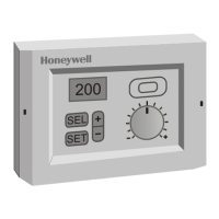
Describes display elements and how to change controller operating modes.

Temperature Sensor Calibration

Calibrates temperature sensor inputs T1, T2, and T3.

Economizer and Damper Control

Activates economizer mode and sets minimum damper position.

Actuator Run Time Configuration

Configures actuator synchronization run time for outputs.

Controller Operation Modes

Navigating Operating Modes

Explains how to navigate between different controller operating modes.

Display and Parameter Adjustment

Displaying Actual Values

Describes how to select and display actual values on the controller.

Selecting and Adjusting Parameters

Explains how to select and adjust configuration or parameter values.

Resetting Parameters and Overriding Outputs

Details resetting parameters to defaults and manually overriding output values.

Schedules and Holidays (RTC)

Weekly Schedule Programming

Details programming the weekly schedule for controller modes.

Holiday Schedule Programming

Details programming holiday types (H1, H2, H3) for specific days.

Clock and Schedule Programming

Selecting Clock and Schedules

Selects between clock, standard schedule, or holiday schedule for programming.

Adjusting Date and Time

Adjusts the real-time clock (date and time).

Standard Schedule Programming

Programs schedule points for weekdays and holiday types.

Error Handling and Interpretation

Analog Input Error Identification

Identifies and displays errors for defective analog inputs (T1, T2, T3, XwRh).

Notes for RTC Controllers

Related product manuals