4
EN
2. General information
These operating instructions are only valid for Honeywell Fall Protection fall arresters for loads.
Only the manufacturer is allowed to modify the device.
The user has to take notice of the actual Regulations (laws, regulations, rules for accident prevention, technical
regulations) see attachment page 3.
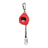
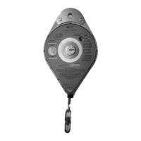
3. Description of the fall arrester
The fall arrester for loads consists of a steel housing containing a rope drum pretensioned by a spring.
This spring tension guarantees that the lanyard is tensioned permanently and consequently that the
brake is activated immediately in case of a fall. The brake reacts to a rope extraction speed of approxima-
tely 0,35 m/s – 1,75 m/s and slows the falling load down so that the stopping distance is up to ca. 800mm
(depending on load and device type). More exact values are added in the technical data.
It is no aloud to make a combination of the load arrester with other devices or other equipment for example
system parts of personal security equipment.
4. Technical data
The Load arrester is build with proper special ropes depending on type of construction.
Device Version SAP code Max.Load (kg) V1 [m/s] V2 [m/s] Ø drop height
[m]
Lasi 5 m / 6-2550L Standard 1006609 250 0,35 0,45 0,75
Lasi 10 m / 6-2000L Standard 1006603 500 0,45 0,65 0,65
Lasi 15 m / 6-2400L Standard ME13732 500 0,50 0,65 1,20
Lasi 30 m / 6-2400L Standard ME21505 240 0,50 0,70 0,60
Max. Load - Maximum load without idler pulley
V1 - Max. rope pull velocity where the device does not arrest
V2 - Min. rope pull velocity where the device does sure arrest
Version T - modified with TOPPAS-springs for higher arrest velocity
Version TB - modified with TOPPAS-springs in Pos.B for higher arrest velocity
Version TA - modified with TOPPAS-springs in Pos.A for higher arrest velocity
Ø drop height - average fall distance of max. load without idler pulley
Operating instructions
Fall arrester for loads
Type 6-2550 L / 6-2000L / 6-2400L
in according to EN 360
Devices are conform to EC machinery directive 2006/42/EG
minimum load: 30 kg
1. Characterization of the fall arrester
- Manufacturer’s name and address:
Honeywell Fall Protection France SAS
35-37, rue de la Bidauderie
18100 VIERZON CEDEX - FRANCE
TéI: (33) 02 48 52 40 40
Fax : (33) 02 48 71 04 97
e-mail: techniserv.hsp@honeywell.com
Web: www.honeywellsafety.com
Serial-Number:
(watch mark on housing)
Next service:
(watch proof label)
!Control Card attachment page 2!
NT90024681 ver A.indd 4 16.02.16 10:41
 Loading...