EasyManua.ls Logo

Honeywell Minipeeper C7027A - User Manual

Honeywell Minipeeper C7027A
12 pages
To Next Page IconTo Next Page
Loading...
PRODUCT DATA
60- 2026- 10
® U.S. Registered Trademark
Copyright © 2000 Honeywell • All Rights Reserved
C7027A, C7035, C7044A, C7927A
Minipeeper® Ultraviolet Flame Detectors
APPLICATION
The C7027A, C7035A, C7044A and C7927A Minipeeper®
Ultraviolet Flame Detectors detect the ultraviolet radiation
emitted by combustion flames. The flame detectors are used
with Honeywell flame safeguard controls to provide flame
supervision for gas, oil, or combination gas-oil burners.
FEATURES
C7027A, C7035A, and C7044A Flame Detectors are
used with R7249A, R7290A, R7749B and R7849A,B
Amplifiers and the appropriate Honeywell controls.
C7044A may also be used with the following 50 Hz
Honeywell combustion controls/amplifiers:
R4341/R7323
R4343/R7323
R4344/R7323
C7027A has an integral collar threaded (internal
1/2-14 NPSM) for mounting on a one-half-inch sight
pipe.
C7035A has an integral collar threaded (internal
1-11-1/2 NPSM) for mounting on a one-inch sight pipe.
C7035A housing meets Underwriters Laboratories Inc.
requirements for rain tightness and complies with
NEMA enclosure standards, types 4 and 4X.
C7044A mounts with a two screw bracket. The UV
sensor tube is enclosed in a stainless steel housing.
C7044A has the capability of side or end viewing in
flame monitoring applications.
Because of their compact size, the C7027A and
C7044A are particularly suitable for blast tube
mounting.
Properly installed, the C7027A and C7035A are
pressure rated for 5 psi.
C7035A ultraviolet radiation sensor tube is field
replaceable.
Two C7027A, C7035A or C7044A Flame Detectors can
be wired in parallel for difficult flame sighting
installations.
C7927A is used with only the R7851B Flame Amplifier
and the appropriate Honeywell controls.
C7927A has an integral collar threaded (internal
1/2-14 NPSM) for mounting on a one-half inch sight
pipe.
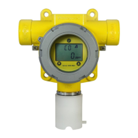
C7027A
C7035A
C7044A
C7927A
Contents
Application ........................................................................ 1
Features ........................................................................... 1
Specifications ................................................................... 2
Ordering Information ........................................................ 2
Installation ........................................................................ 4
Wiring (All Models—Fig. 10) ............................................. 8
Adjustments and Checkout .............................................. 9
Troubleshooting ................................................................ 12
Maintenance ..................................................................... 12
Question and Answer IconNeed help?

Do you have a question about the Honeywell Minipeeper C7027A and is the answer not in the manual?

Honeywell Minipeeper C7027A Specifications

General IconGeneral
BrandHoneywell
ModelMinipeeper C7027A
CategorySecurity Sensors
LanguageEnglish

Summary

Application

Features

Specifications

C7027 A Flame Detector Specifications

Details ambient operating temperature, maximum pressure, mounting, and wiring for the C7027A detector.

C7035 A Flame Detector Specifications

Details flame detection, temperature ratings, pressure, mounting, wiring, and approvals for the C7035A detector.

C7044 A Flame Detector Specifications

Details flame detection, mounting, and wiring for the C7044A detector.

C7927 A Flame Detector Specifications

Details temperature ratings, pressure, mounting, wiring, and approvals for the C7927A detector.

Ordering Information

Installation

Installation Safety Precautions

Highlights critical safety steps and warnings for installing the flame detectors, emphasizing careful reading and electrical safety.

Mounting Procedures

Covers mounting the detectors using sight pipes, including preparing the combustion chamber and mounting the sight pipe.

Wiring Connections

Provides instructions and cautions for wiring the flame detectors, including wire type and connections.

Adjustments and Checkout

UV Sensor Tube Test

Instructs on testing the UV sensor tube during initial burner lightoff to ensure proper function.

Detector Sighting Position Adjustment

Guides on adjusting the detector's position for optimum flame signal measurement using microamps or voltage.

Ignition Spark Response Test

Details how to test that ignition spark does not falsely activate the flame relay.

Final Checkout Procedure

Outlines the final steps to verify correct operation by checking the installation and running the burner through a cycle.

Troubleshooting

Inadequate Flame Signal

Provides steps to diagnose and resolve issues leading to an inadequate flame signal from the detector.

Maintenance

Periodic Maintenance

Recommends cleaning the viewing window and sight pipe, and notes the UV sensor tube life expectancy.

Cleaning C7044 A Detector

Details the procedure for cleaning the viewing window of the C7044A detector.

Related product manuals