EasyManua.ls Logo

Honeywell Minipeeper C7035A - User Manual

Honeywell Minipeeper C7035A
12 pages
Print Icon
To Next Page IconTo Next Page
Loading...
PRODUCT DATA
60-2026-16
Minipeeper
®
Ultraviolet Flame
Detectors
C7027A, C7035A, C7044A, C7927A
APPLICATION
The C7027A, C7035A, C7044A and C7927A Minipeeper
®
Ultraviolet Flame Detectors detect the ultraviolet radiation
emitted by combustion flames. The flame detectors are used
with Honeywell flame safeguard controls to provide flame
supervision for gas, oil, or combination gas-oil burners.
FEATURES
C7027A, C7035A, and C7044A Flame Detectors are used
with RA890G devices or R7249A, R7290A, R7749B and
R7849A,B Amplifiers and the appropriate Honeywell
controls.
C7927A is used with only the R7851B Flame Amplifier and
the 7800 SERIES controls.
C7044A may also be used with the following 50 Hz
Honeywell combustion controls/amplifiers:
R4341/R7323
R4343/R7323
R4344/R7323
C7027A/C7927A has an integral collar threaded (internal
1/2-14 NPSM) for mounting on a one-half-inch sight pipe.
C7035A has an integral collar threaded (internal
1-11-1/2 NPSM) for mounting on a one-inch sight pipe.
C7035A housing meets Underwriters Laboratories Inc.
requirements for rain tightness and complies with NEMA
enclosure standards, types 4 and 4X.
C7044A mounts with a two screw bracket. The UV sensor
tube is enclosed in a stainless steel housing.
C7044A has the capability of side or end viewing in flame
monitoring applications.
Because of its compact size, the C7044A is particularly
suitable for blast tube mounting.
Properly installed, the C7027A, C7035A and C7927 are
pressure rated for 5 psi.
C7035A ultraviolet radiation sensor tube is field
replaceable.
Two C7027A, C7035A or C7044A Flame Detectors can be
wired in parallel for difficult flame sighting installations.
(C7927cannot be used in parallel.)
C7927A1016, C7027A1049, C7027A1064, C7027A1072
come with 1/2-in. spud connection for electrical wiring.
C7927 is immune to x-ray testing.
C7027A
C7035A
C7044A
C7927A
M33825
Contents
Application ........................................................................ 1
Features ........................................................................... 1
Specifications ................................................................... 2
Ordering Information ........................................................ 2
Wiring (All Models—Fig. 9) ............................................... 8
Adjustments and Checkout ............................................... 9
Troubleshooting ................................................................ 12
Maintenance ..................................................................... 12
Question and Answer IconNeed help?

Do you have a question about the Honeywell Minipeeper C7035A and is the answer not in the manual?

Summary

Application

Features

C7027 A, C7035 A, and C7044 A Flame Detectors

Used with RA890G devices or R7249A, R7290A, R7749B and R7849A,B Amplifiers and controls.

C7927 A Flame Detectors

Used with R7851B Flame Amplifier and the 7800 SERIES controls.

Specifications

C7027 A Minipeeper Ultraviolet Flame Detector

Ambient operating temp, pressure, mounting, wiring, dimensions, and notes.

Ordering Information

Contacting Honeywell for purchasing and product information.

C7035 A Minipeeper Ultraviolet Flame Detector

C7044 A Minipeeper Ultraviolet Flame Detector

C7927 A Minipeeper Ultraviolet Flame Detector

Installation

When Installing This Product

General instructions and safety precautions before installation.

Important Notes on Detector Lifespan

Notes on detector lifespan and burner cycling requirements.

Warning: Explosion and Electrical Shock Hazard

Basic Requirements For Ultraviolet Detector Installations

Key factors for UV detector installation, line-of-sight, and flame sighting.

Other Radiation Sources Sensed By The UV Detector

Ultraviolet Sources

Lists various UV sources like refractory, spark, welding arcs, and lamps.

Gamma Ray and X-ray Sources

Lists sources like diffraction analyzers, electron microscopes, and radioisotopes.

Mounting a C7027 A, C7927 or C7035 A

Locate the Sight Pipe

Guidance on selecting and preparing the sight pipe for installation.

Prepare Hole In Wall Of Combustion Chamber

Instructions for cutting and flaring the hole for the sight pipe.

Mounting The Sight Pipe

Steps for threading, cutting, and positioning the sight pipe.

Sight Pipe Ventilation

Methods for ventilating the sight pipe for cooling or clearing.

Swivel Mount

Mount The Detector

Using a Heat Block With a C7027 or C7927

Mounting a C7044 A On a Blast Tube

Warning: Explosion Hazard

Safety warning regarding locating the C7044 in atmospheres with fuel vapors.

Wiring (All Models)

Caution: Equipment Damage Hazard

Warning about incorrect wiring polarity causing improper supervision.

Notice: Industry Standards

Requirement for conduit seals for flammable gas/liquid flow protection.

Important: Wiring Compliance

Emphasizes compliance with local codes and NEC Class 1 wiring.

Adjustments and Checkout

UV Sensor Tube Test

Procedure to test the UV sensor tube for proper operation.

Adjust Detector Sighting Position

How to adjust detector position for optimum flame signal.

Measuring Flame Signal

Pilot Turndown Test

Procedure to test pilot flame proving before main fuel valve opens.

Table 1. Flame Signal

Ignition Spark Response Test

Response to Other Ultraviolet Sources

Weld The Sight Pipe (or Tighten the C7044 A Clamp Screw)

Final Checkout

Troubleshooting

Warning: Electrical Shock Hazard

Caution regarding line voltage presence during troubleshooting.

Inadequate Flame Signal

Steps to diagnose and resolve issues with obtaining a flame signal.

Maintenance

Periodic Maintenance

Guidance on cleaning and replacing components for optimal performance.

Cleaning the C7044 A Detector

Specific procedure for cleaning the C7044A detector.

Overview

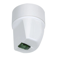
The Honeywell Minipeeper® Ultraviolet Flame Detectors, including models C7027A, C7035A, C7044A, and C7927A, are designed to detect ultraviolet (UV) radiation emitted by combustion flames. These detectors are integral components of Honeywell flame safeguard controls, providing flame supervision for gas, oil, or combination gas-oil burners.

Function Description

The primary function of these detectors is to sense the presence of a flame by detecting its UV radiation. This signal is then fed to a flame safeguard control, which uses it to ensure safe burner operation. If the flame is not detected when expected, or if it extinguishes unexpectedly, the control system will initiate a safe shutdown. The C7027A, C7035A, and C7044A models are compatible with RA890G devices or R7249A, R7290A, R7749B, and R7849A,B Amplifiers, as well as appropriate Honeywell controls. The C7927A is specifically designed for use with the R7851B Flame Amplifier and the 7800 SERIES controls.

Important Technical Specifications

  • Flame Detection: All models detect UV radiation. The C7035A offers end viewing, while the C7044A housing has two openings for either side or end viewing, with side viewing being 1/8 as sensitive as end viewing.
  • Ambient Operating Temperature Ratings:
    • C7027A: 0°F to 215°F (-18°C to 102°C), or -40°F to 215°F (-40°C to +102°C), depending on model.
    • C7035A: 0°F to 250°F (-18°C to +121°C), or -40°F to 250°F (-40°C to +121°C), depending on model.
    • C7927A1016: -40°F to +200°F (-40°C to +93°C).
  • Storage Temperature Rating (C7927A): -20°F to +120°F (-28°C to +49°C).
  • Maximum Pressure Rating: All models are pressure rated for 5 psi (34.5 kPa).
  • Mounting:
    • C7027A/C7927A: Integral collar threaded (internal 1/2-14 NPSM) for mounting on a 1/2-inch sight pipe.
    • C7035A: Integral collar threaded (internal 1-11-1/2 NPSM) for mounting on a one-inch sight pipe. The DIN approved C7035A1064 has 1-11 BSP.P1 threads.
    • C7044A: Mounts with a two-screw bracket (included in the Bag Assembly).
  • Wiring Connections:
    • C7027A: Two 8 ft (2.44 m), color-coded, plastic-insulated, 18 AWG, NEC Class 1 lead wires, rated for 221°F (105°C). Rear has a clamp type connector for 1/2 in. flexible metallic conduit. Models are available with 1/2 in. internally threaded spud connector. C7027A1064 has 24 ft (7.32 m) lead wires. C7027A1114 has 44 in. (1.118 m) lead wires and 22 in. (558 mm) flexible conduit.
    • C7035A: Two 6 ft (1.83 m), color-coded Silicon Rubber Insulated 18 AWG, NEC Class 1 lead wires rated for 302°F (150°C). Rear has 1/2-14 NPSM internal threads for conduit connection. The DIN-approved C7035A1064 has 1/2-14 BSP-F threads. C7035A1056 has 12 ft (3.66 m) leadwires. C7035A1080 has 10 foot (3 Meter) leadwire rated for 600°F (316°C).
    • C7044A: Two 8 ft (2.44 m) color-coded, plastic coated 18 AWG, NEC Class 1 lead wires. Rear has a clamp type connector for 1/2 in. flexible metallic conduit.
    • C7927A: Two 8 ft (2.4 m) color-coded, plastic coated 18 AWG, NEC Class 1 lead wires. Rear has a 1/2-in. spud-type connector.
  • Approvals: Underwriters Laboratories Inc. (listed: File No. MP268), Canadian Standards Association certified (Master Report LR 95329-1), Factory Mutual approved, Swiss Re (formerly Industrial Risk Insurers) acceptable. C7927A is cUL listed (MP268, Volume 30 and 31) and FM Approved (report number 3011020, June 26, 2002).
  • C7035A Housing: Meets Underwriters Laboratories Inc. requirements for rain tightness and complies with NEMA enclosure standards, types 4 and 4X.
  • C7927: Immune to x-ray testing.

Usage Features

  • Compact Size (C7044A): Particularly suitable for blast tube mounting.
  • Side or End Viewing (C7044A): Offers flexibility in flame monitoring applications.
  • Field Replaceable Sensor Tube (C7035A): The ultraviolet radiation sensor tube can be replaced in the field. For C7027A, C7044A, and C7927A, the sensing tube is not field replaceable, requiring replacement of the entire detector.
  • Parallel Wiring: Two C7027A, C7035A, or C7044A Flame Detectors can be wired in parallel for difficult flame sighting installations, reducing nuisance shutdowns. Note that C7927 cannot be used in parallel. When paralleling, the minimum ambient operating temperature must be increased to 32°F (0°C) for detectors rated for 0°F (-18°C), or to -10°F (-23°C) for detectors rated for -40°F (-40°C).
  • Ignition Spark Response Mitigation: For C7027A, C7035A, and C7044A applications where ignition spark response cannot be avoided, the Q624A or Q652B Solid-State Ignition Transformer can be used to alternately activate the spark generator and the UV sensing tube, preventing false flame signals.
  • Sight Pipe Installation: A black iron pipe is recommended for the sight pipe. It should be located to provide a clear line-of-sight to the flame, preferably tilting downward to prevent soot or dirt buildup. The pipe length and sighting angle are critical and should be determined during installation.
  • Sight Pipe Ventilation: Ventilation may be necessary to cool the detector or clear the sight pipe of UV-absorbing substances. For negative pressure chambers, drilling holes in the sight pipe or using a perforated nipple allows air flow. For positive pressure chambers, pressurized air from the burner blower can be connected to the sight pipe.
  • Heat Block (Accessory): The 136733 Heat Block is available for C7027A or C7927A when sight pipe temperatures exceed 215°F (102°C) but are below 266°F (130°C).
  • Swivel Mount (Accessory): The 118367A Swivel Mount facilitates proper sighting adjustments.
  • UV Sensor Tube Life Expectancy: The C7027, C7035, and C7044 ultraviolet radiation sensing tubes have a life expectancy of 40,000 hours of continuous use within specified ambient temperature and voltage ratings. When a tube wears out, it will fail to properly discriminate between flame conditions.
  • Burner Cycling: These detectors should only be used on burners that cycle on/off or are periodically checked for proper operation. Industry guidelines suggest one burner cycle in a 24-hour period.
  • Earth Ground: The detector and flame safeguard control must be connected to earth ground, typically via a flexible conduit or a good ground connection at the mounting bracket.
  • Wiring Considerations: Lead wires should be kept as short as possible to minimize capacitance. Splices, if needed, should be made in a junction box using moisture-resistant no. 14 wire. F and G wires must be run in their own conduit, separate from other power-carrying lead wires. Shielded twisted pair wire can be used for the F leadwire, with the shield grounded to the G terminal at the flame safeguard wiring subbase. Scanner wires should be separated a minimum of two inches (51 mm) from other line voltage wires in the main control panel.

Maintenance Features

  • Periodic Cleaning: The viewing window and sight pipe (if used) should be cleaned periodically with a soft, clean cloth to remove contaminants from the UV radiation sensor tube glass envelope.
  • Sensor Tube Replacement: For C7035A, the ultraviolet sensing tube can be replaced. For C7027, C7927, or C7044, the entire detector should be replaced at appropriate intervals based on the 40,000-hour life expectancy.
  • System Adjustment: The flame detection system should be kept adjusted for smooth, reliable operation as recommended by the burner manufacturer.
  • C7044A Cleaning Procedure: To clean the C7044A, loosen the two screws holding the mounting bracket to the blast tube, twist the bracket and detector to remove, clean the viewing window, and then reinsert and tighten the screws. The clamp screw on the bracket should not be loosened.

Honeywell Minipeeper C7035A Specifications

General IconGeneral
BrandHoneywell
ModelMinipeeper C7035A
CategorySecurity Sensors
LanguageEnglish

Related product manuals