SERIES 90 MODUTROL IV™ MOTORS
7 63-2631
Wiring
CAUTION
Electrical Shock or Equipment Damage Hazard.
Can shock individuals or short equipment
circuitry.
Disconnect power supply before installation.
IMPORTANT
All wiring must agree with applicable codes,
ordinances and regulations.
1. Ensure that the voltage and frequency stamped on the
motor correspond to the power supply characteristics.
2. When connecting several motors in parallel, ensure that
the power supply VA rating is large enough to provide
power to all motors used without overloading.
3. Fig. 9 shows that the motor terminals are
quick-connects located on top of the printed circuit
board.
4. To access the wiring compartment:
a. Remove the four screws from the junction box top.
b. Lift off the cover.
5. Refer to Fig. 5 for typical wiring, and Fig. 7 for internal
auxiliary switch connections.
NOTE: Reverse motor rotation by switching wires at either
the motor or the panel. Reverse rotation on the Series
90 models by reversing the wires at terminals W
and B.
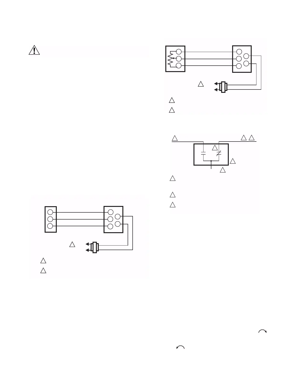
Fig. 5. Typical Series 90 wiring.
Fig. 6. Wiring for potentiometer control.
Fig. 7. Auxiliary switch schematic.
SETTINGS AND ADJUSTMENTS
Before Setting Stroke
1. Remove the top cover from the motor.
2. Disconnect the controller from the motor.
3. Connect a potentiometer to the motor as shown in Fig. 6.
IMPORTANT
Detach linkage from motor before adjusting stroke.
Adjustable Stroke
The stroke adjustment is made by means of two
potentiometers, the stroke and sensitivity potentiometers.
When viewing from the power end of the motor, the stroke
potentiometer is to the far left and sensitivity potentiometer is
to the far right (see Fig. 8). To set the stroke to 160° (maximum
position) turn the both potentiometers fully clockwise ,
using a 1/8 in. straight-blade screwdriver. To set the stroke at
90° (minimum position) turn both potentiometers fully counter-
clockwise .
L1
(HOT)
L2
1
1
2
R
W
B
R
W
B
T1
T2
TRANSFORMER
POWER SUPPLY. PROVIDE DISCONNECT MEANS AND
OVERLOAD PROTECTION AS REQUIRED.
TRANSFORMER MAY BE INTERNAL OR EXTERNAL
M770A
SERIES 90
CONTROLLER
MOTOR
L1
(HOT)
L2
1
1
2
R
W
B
R
W
B
T1
T2
TRANSFORMER
POWER SUPPLY. PROVIDE DISCONNECT MEANS AND
OVERLOAD PROTECTION AS REQUIRED.
TRANSFORMER MAY BE INTERNAL OR EXTERNAL
M13708
135 OHM
POTENTIOMETER
MOTOR
BLUE LEAD
YELLOW LEAD
RED LEAD
USE NEC CLASS 1 WIRING UNLESS POWER SUPPLY
MEETS CLASS 2 REQUIREMENTS. TAPE UNUSED LEADS.
ENSURE THE CURRENT DRAW OF THE EXTERNAL CIRCUIT
IS LESS THAN SWITCH CONTACT RATING.
ON TWO-SWITCH MOTORS, SECOND SWITCH HAS BLACK
LEADS WITH BLUE, YELLOW, AND RED TRACERS.
SOME AUXILIARY SWITCH ASSEMBLIES INCLUDE ONLY
RED AND YELLOW LEADS. SOME OTHERS DO NOT INCLUDE
THE YELLOW LEAD.
M17099
1
1
1
2
2
2
2
3
3
 Loading...