SERIES 90 MODUTROL IV™ MOTORS
9 63-2631
CAUTION
Careless Installation Hazard.
Use of excessive force while adjusting cams
damages the motor.
To avoid damaging motor end switches, set cams by
moving only the top of the screwdriver.
CAUTION
Careless Installation Hazard.
Forcibly turning the motor shaft damages the gear
train and stroke limit contacts.
Never turn motor shaft manually (by hand or with a
wrench).
CAUTION
Equipment Damage Hazard.
Can damage the motor beyond repair.
Set cams by moving the top of the screwdriver only.
Pressing screwdriver against cam slot sides or use of
excessive force can damage motor end switches.
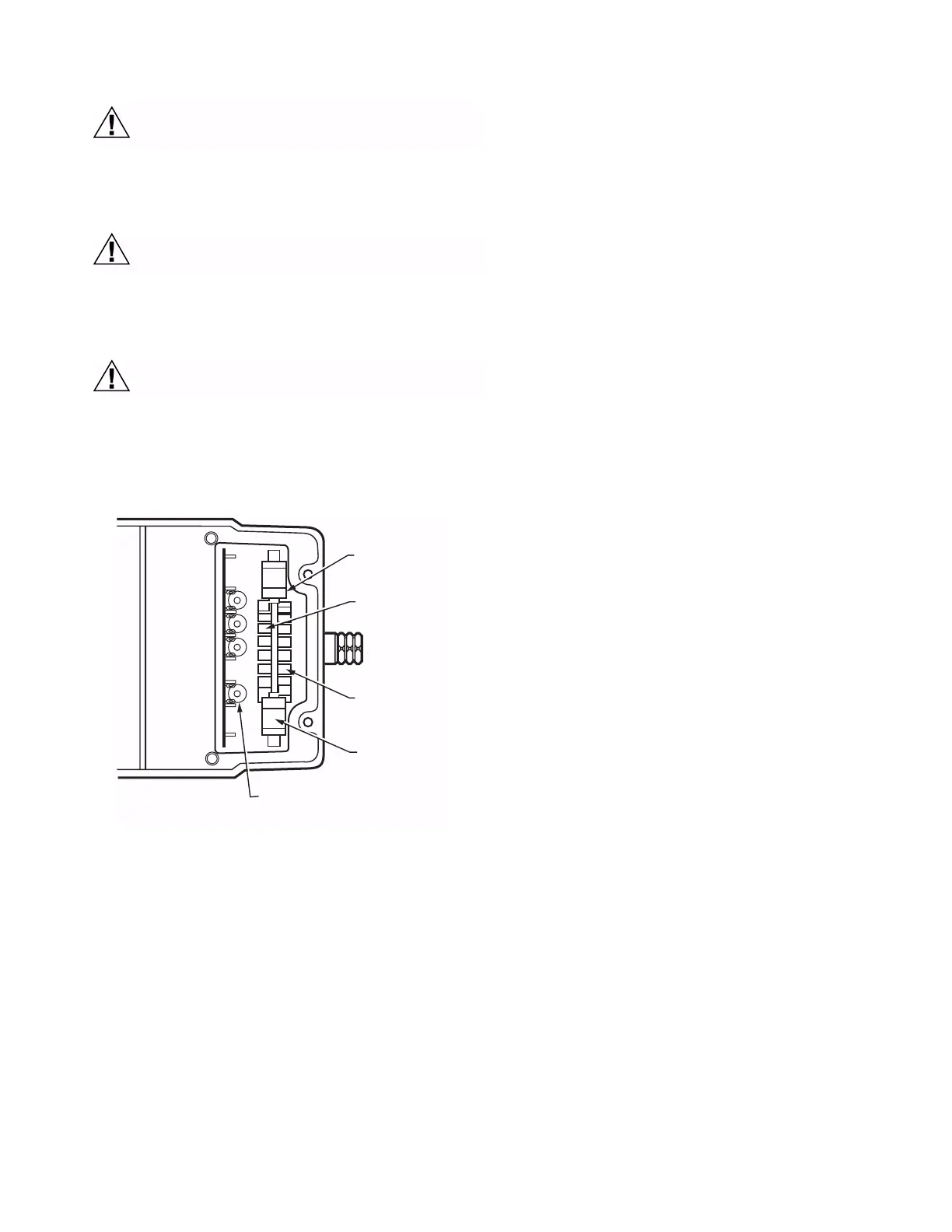
Fig. 9. Terminals and adjustments.
Auxiliary Switches
Adjustable cams actuate the auxiliary switches. These cams
can be set to actuate the switches at any angle within the
stroke of the motor. Select switch differential of 1° or 10°.
Motors with factory-added auxiliary switches are shipped in the
closed position (fully counterclockwise, as viewed from the
power end). Auxiliary cam default actuates the switches 30°
from full open with a 1° differential. With the motor in the closed
(fully counterclockwise) position, the auxiliary switch breaks
contacts R-B. See Fig. 7 (or the auxiliary switch Instruction
Sheet) for auxiliary switch wiring.
NOTE: Auxiliary switches can only be added to motors that
include auxiliary switch cams. (These cams cannot be
field-added.)
NOTE: Series 2 Motors are shipped with auxiliary switch
cams that permit acceptance of 220736A,B Internal
Auxiliary Switch Kits. Refer to Form no. 63-2228 for
220736A,B Installation Instructions.
Auxiliary Switch Adjustment
1. Remove the top cover from the motor to gain access to
the motor terminals and auxiliary cams.
2. Disconnect the controller from the motor.
3. Connect a potentiometer to the motor as shown in Fig. 6.
4. Using the potentiometer, drive the motor to the position
where the auxiliary equipment is to be switched.
5. For a 1° switch differential, check continuity of the
auxiliary switch contacts R-B and rotate the cam as
follows:
a. If the contacts are open, rotate the cam clockwise
until the R-B contacts close.
b. If the contacts are closed, rotate the cam
counterclockwise until the R-B contacts open.
6. For a 10° switch differential:
a. Spring return models: rotate the cam approximately
180° so that the slow-rise portion of the cam
actuates the switch. Then check continuity of the
auxiliary switch contacts R-B
b. Non-spring return models: check continuity of the
auxiliary switch contacts R-B.
7. Rotate the cam as follows:
a. If the contacts are open, rotate the cam
counterclockwise until the R-B contacts close.
b. If the contacts are closed, rotate the cam clockwise
until the R-B contacts open.
8. Check for proper auxiliary equipment differential and
switching by driving the motor though the full stroke in
both directions.
9. Disconnect the potentiometer, reconnect the controller,
and replace the motor top cover.
NOTE: Changing the differential from 1° to 10° reverses the
switching action. For example, with a 10° differential,
switch contacts R-B make and R-W break on a
counterclockwise (closed) rotation. With a 1°
differential, switch contacts R-W make and R-B break
on a counterclockwise (closed) rotation.
INNER AUXILIARY
SWITCH
INNER AUXILIARY
SWITCH CAM (BLUE)
POWER
END
OUTER AUXILIARY
SWITCH CAM (RED)
OUTER AUXILIARY
SWITCH
ADJUSTABLE STROKE POTENTIOMETER
NOTE: NOT ALL FEATURES AVAILABLE ON ALL MODELS.
M13707
W
B
R
T
2
T
1
 Loading...