MP909E UL LISTED DAMPER ACTUATOR
95-6076
4
Normally Open
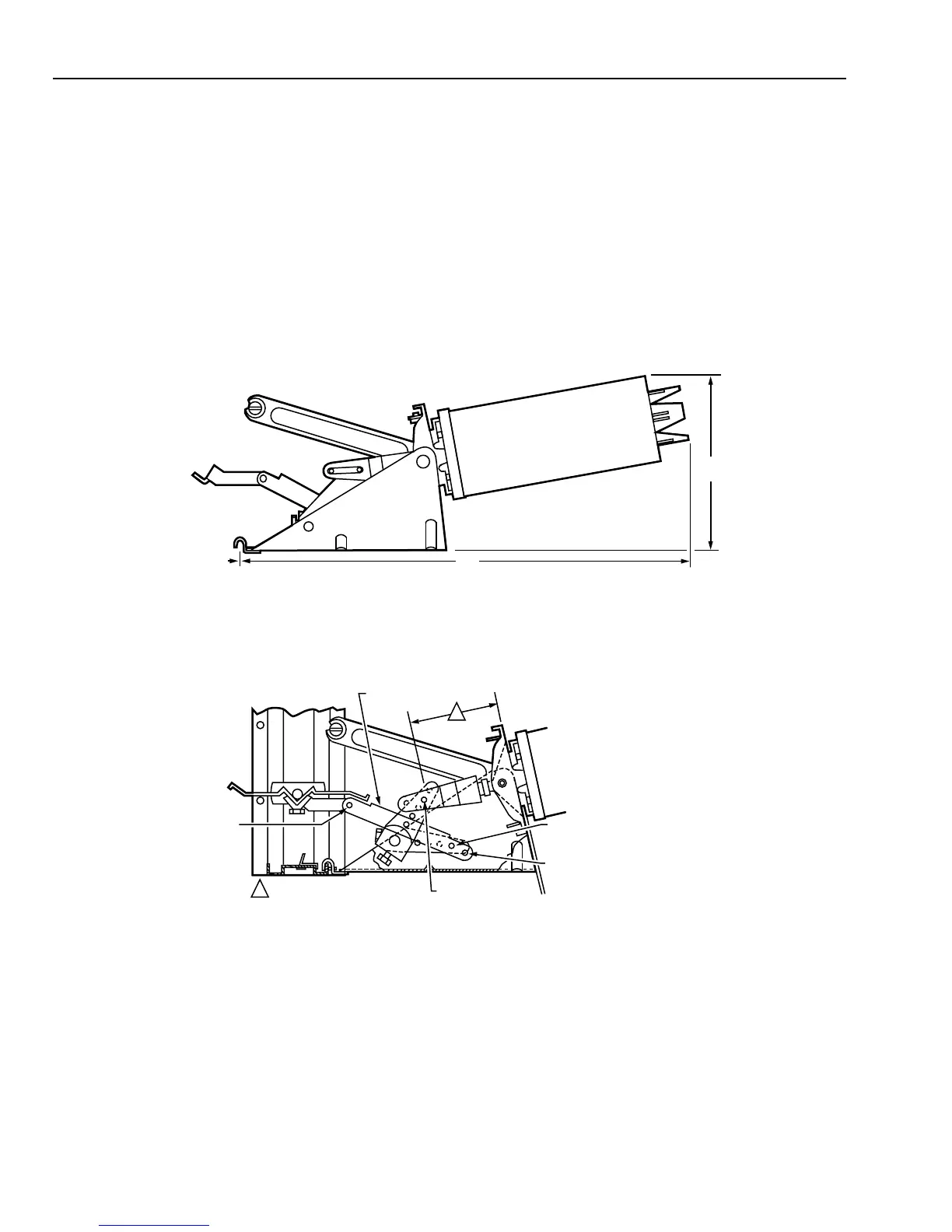
1 For internal mounting dimensions, see Figure 7.
2 Check faceplate position (Fig. 6). Adjust faceplate
position if necessary.
3 Use 1/8-inch Allen wrench to loosen set screws on
mounting clamp (Fig. 6) one turn. Remove and discard
shipping stop.
4 Determine height of damper drive blade. Dampers
with 10, 12, 18, 26, 34, and 42-inch B dimensions
have 8-inch drive blades. All others have 6-inch drive
blades.
5 For installation with 6-inch drive blades, go to Step 6.
For installation with 8-inch drive blades, remove clevis
pin A (Fig. 8) and reinstall in pushrod hole marked 8.
(Hole in crankarm marked 90.)
6 Locate factory installed drive ear on damper. (Mounted
per Damper Ordering Instructions.) Actuators must be
mounted only in this (these) position(s).
7 Loosen truss link to actuator base mounting screw.
Remove clevis pin C from damper pushrod.
8 Set actuator in place by hooking mounting clamp over
bottom edge of damper frame.
9 Connect damper pushrod to damper drive ear with
clevis pin.
J Tighten set screws on mounting clamp.
K Connect truss link to damper and tighten both truss link
screws. Truss link must be bent slightly.
17
(430)
EDGE OF
DAMPER
6-1/2
(165)
C8213
MP909E
Fig. 7. Internal Mounting Normally Open Dimensions in Inches (Millimeters).
C8214
1
1
REFERENCE DIMENSIONS:
4-INCH STROKE (FACTORY
SET) = 3-3/16 INCH (81 MM)
CLEVIS
PIN C
CLEVIS PIN B
(FACTORY INSTALLED)
DAMPER
PUSHROD
CLEVIS PIN "A" LOCATION
FOR 8-INCH DRIVE BLADE
CLEVIS PIN "A" LOCATION
FOR 6-INCH DRIVE BLADE
(FACTORY INSTALLED)
Fig. 8. Internal Mounting Normally Open Installation.
Piping
Special piping is required for Leakage Rated (Smoke)
Damper actuators. The piping from the actuator to the device
which interfaces to the smoke control system must be 1/4-inch
copper tubing or as required by local code. 1/4-inch polyester
tubing pigtails are provided with the actuator to interface with
the copper tubing.
Figure 9 shows how to adapt 1/4-inch copper tubing to
polyester tubing. CCT1635B compression adapters connect
the 1/4-inch copper tubing to the 1/4-inch polyester. These
adapters must be ordered separately.
Copper tubing can be connected directly to the actuator as
shown in Figures 10 and 11.
 Loading...